Results 1 to 14 of 14

Thread: Mahogany rudder project

  1. #1
    Join Date
    Jan 2010
    Location
    Connecticut
    Posts
    661

    Mahogany rudder project

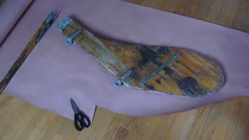
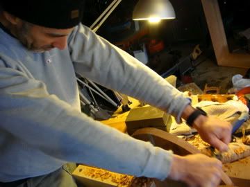
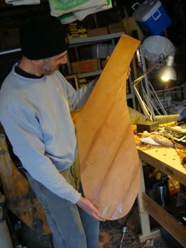
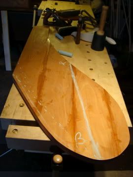
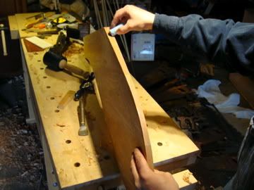
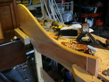
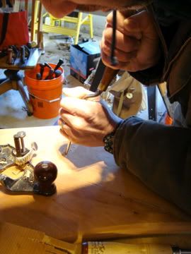
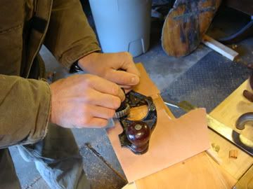
    Hello boat building forum enthusiasts and lurkers! I usually hang out at the Neanderthal Haven fixing old saws, but a friend of mine recently got a boat and is in the process of fixing it. The rudder is busted up (please see photos) and we are in the process of making another. Could I solicit your expertise?

    Here's the plan, please sound off if anything sounds awry:

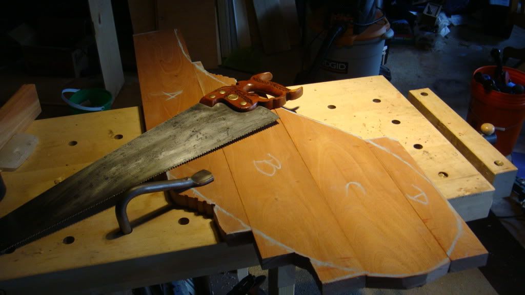
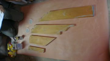
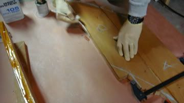
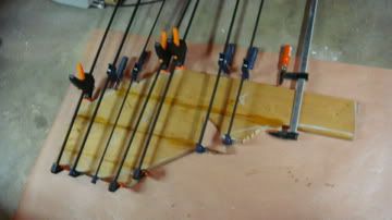
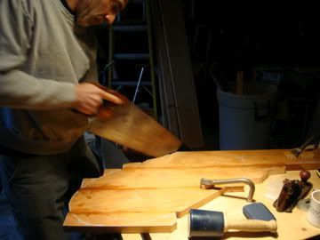
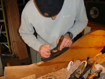
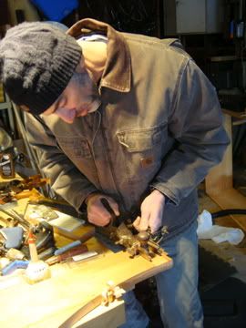
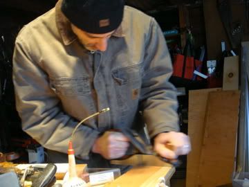
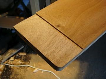
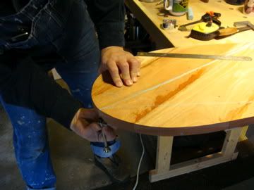
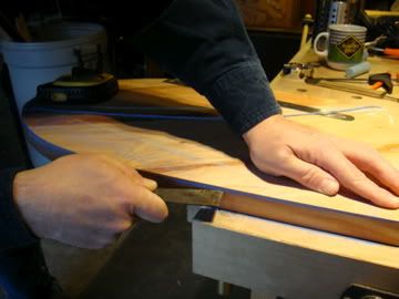
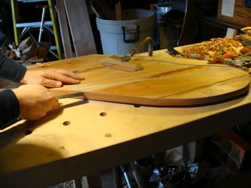
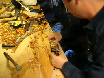
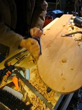
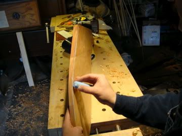
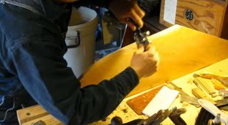
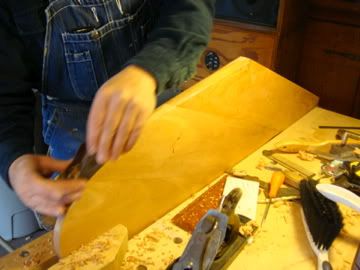
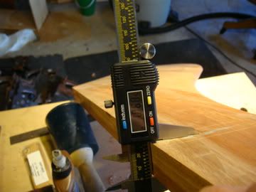
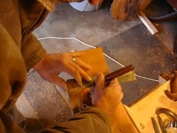
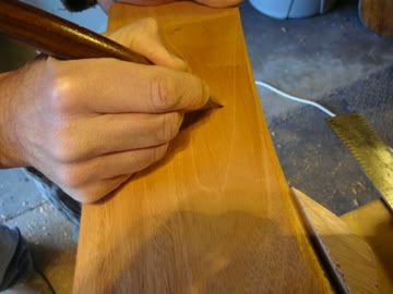
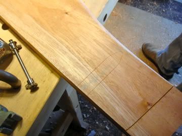
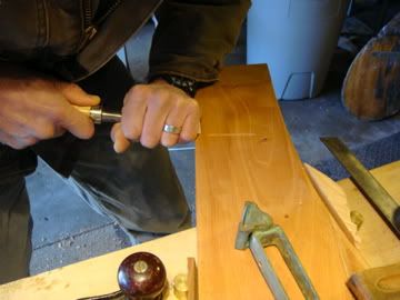
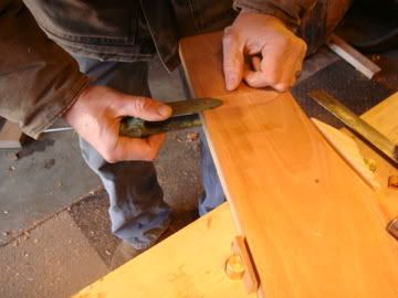
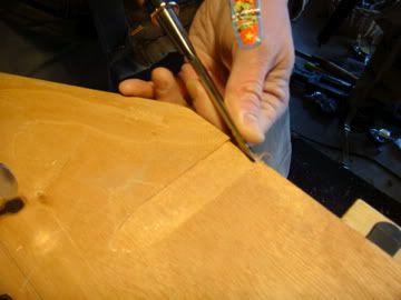
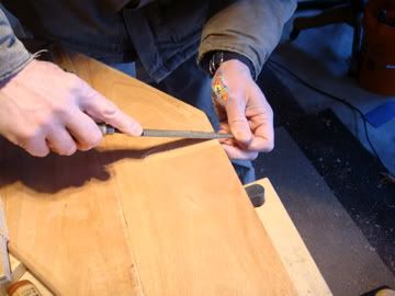
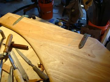
    We've got a 98-inch plank of 4/4 mahogany that's 5.5 wide. We plan to simply laminate it together with marine epoxy and clamps, trim it with saws to resemble the old rudder, shape it and round-over the edges with planes and spokeshaves, cover it with more marine epoxy and polyurethane, and attach the hardware.

    rudder1.jpg

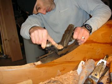
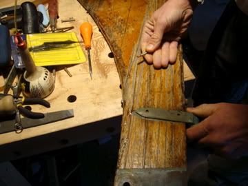
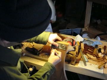
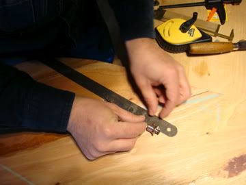
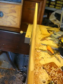
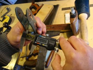
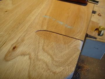
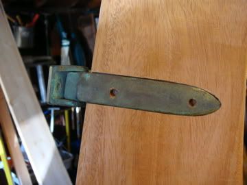
    The previous rudder has threaded rod ("drifts?") running through it (see second photo) as well as a brass reinforcement strap. These seem to me like repairs that would not be necessary on a new rudder, but contradict me by all means if those would be advisable.

    rudder2.jpg

    Sadly, I can provide little in the way of graphic representations of nautical sauciness or few details about the boat--if there's interest I'll take photos. (I can take photos if there's interest!) It's a 12 - 14 foot sailboat with a fiberglass hull and transom. There is an iron or steel keel. It has an aluminum mast about 16 - 18 feet tall. Thanks in advance for your suggestions and replies.

  2. #2
    Join Date
    Aug 2006
    Location
    south jersey
    Posts
    355
    You should post this on woodenboat.com. You'll get plenty of info from people who actually epoxy things together and throw them in the water.

  3. #3
    Join Date
    Jul 2003
    Location
    Smithfield, Va
    Posts
    328
    I would install the drifts. They add strength to the rudder ( at least to the original). Depending on your laminating design you may not need them but a little extra insurance in the structural integrity doesn't hurt anything. As for the bronze strap, it looks like that may have added sometime later to help hold an already split rudder together. Rudders can and do see a lot of side force and a rudder of this size on a 12'-14' boat tells me that it also acts something like a centerboard, helping to reduce lateral movement of the boat. Check out the size of the rudders on cat boats.

  4. #4
    Join Date
    Jan 2010
    Location
    Connecticut
    Posts
    661
    Excellent, thanks for the advice. I'm not sure the brass strap was ever in the water because it's held in with galvanized screws that have no oxidation on them. On the subject of the drifts, as I'm fond of saying, "when you've run aground three miles out, the rudder will be sure to let you know what you did wrong." Some follow-up questions:

    Would drift(s) have been included on such a rudder originally?
    Is there a book or resource that comes to mind that would give greater detail?
    Is there a recommended wood grain orientation on such a rudder? As it currently stands, the grain runs straight up and down, with resultant splitting.
    Would drift(s) be better as wedged/peined over on one side and bolted with thread locker on the other?
    Drift material should be Brass? Bronze? Stainless? The pintles are greenish with verdigris (brass?)

  5. #5
    Join Date
    Jul 2003
    Location
    Smithfield, Va
    Posts
    328
    It would appear that the original rudder is made of solid wood rather than plywood in which case the bronze drifts would have been included as standard practice considering the shape of the rudder.
    As for making a new one, I would leave the grain vertical as this will ultimately be the strongest considering the normal loads applied.
    Wedging/peening one end will work however I believe you will find that a nut/ washer on each end will be the easiest.
    Bronze would be my first choice, followed by stainless or monel. Brass is unacceptable.
    Check out Chappel's "Building Classic Small Craft".
    Basically I would try to duplicate the original as closely as possible. It's a time tested and proven design.

  6. #6
    Join Date
    Jan 2010
    Location
    Connecticut
    Posts
    661
    Okay, here's an update! The pictures tell the story thus far.

    Tracing out the original on craft paper


    Transferring the pattern to the mahogany with chalk and sawing up


    Laying out on more craft paper rubbed with paraffin so it won't stick to the floor


    Glueing up with West's Epoxy


    Clamping for 8 - 24 hrs

  7. #7
    Join Date
    Jan 2010
    Location
    Connecticut
    Posts
    661

    Day Two Progress

    Today we trimmed the outside shape of the mahogany rudder. For some reason, everything's going to plan, the work is going well, and aside from a little reversing grain here and there there have been no surprises. I did most of the background work such as sharpening tools, taking pictures, and getting things fastened for my friend, who did the bulk of the fun work. At one point, he asked what plane could we possibly use on a concave portion of the rudder. "The spokeshave," I blurted out. "No, wait. I have the perfect plane for that!!! It'll be the first time I've used it!" The plane was of course a Stanley 113 compass plane. In ten or so minutes I had the blade sharpened up and ready to go. More pics . . . .

    Trimming with a nice Disston No. 16


    Just take a little off the top . . . .


    Stanley No. 113 in action. This turned out to be perfectly suited for this curve.


    Adjusting the amount of concavity. It's unfortunate that the adjustment knob is what you are naturally inclined to want to hold on to while working with this, like a regular bench plane. I think the sole is made of spring steel, and is peined to the frog.


    The No. 113 Compass Plane also adjusts to do convex curves, but the radius on this curve is small enough to warrant a spoke shave instead. It's a real pleasure to use a spokeshave and I'm always looking for excuses to use one.


    The project thus far.


  8. #8
    Join Date
    Jan 2010
    Location
    Connecticut
    Posts
    661

    More progress

    Today we pulled out the hardware from the old fittings. Since they were secured by peined-in rivets, we filed the heads down and tried to pop them out with punches. The rivets turned out to actually be soft copper, so the more we pounded on them, the less they were inclined to come out. Didn't get a photo of it, but we marked the centers of the rivets, and then proceeded to drill them mostly out, first with an eggbeater and 1/8 inch drill bit, then a 13/64 inch drill bit in a bit brace. Finally they submitted to the drift punch (see photo).


    We marked out the rabbets for the brass plate hardware.


    Then we created a rabbet with a Stanley No. 46 Skew mouth plough plane.


    It was a bit uneven so we cleaned it up with an ordinary bench plane.


    The final rabbet: A nice bit of work. Good job Mike!


  9. #9
    Join Date
    Aug 2006
    Location
    south jersey
    Posts
    355
    Wow....and not a bandsaw in sight. Nice work.

  10. #10
    Join Date
    Feb 2003
    Location
    Shoreline, CT
    Posts
    2,923
    What kind of foil shaping do you intend? Rudders tend to have rounded forward ends and taper (though not to a sharp edge) toward the trailng edge.

  11. #11
    Join Date
    Jan 2010
    Location
    Connecticut
    Posts
    661
    Thanks John,

    I've got a band saw but haven't been using it. The curves on this are big enough that we were able to do most everything with hand saws, though I wish I'd had a ship's point version on some of them. I've been avoiding the ship's points because they look like nice saws that have been all used up, and because who could anticipate needing something that specialized? On some of the curves, we drilled a series of holes with an eggbeater and used a coping saw to connect the dots. So far it's a hand tools-only project, and having come this far we're consciously avoiding electrons beyond shop lights.

    Hi Steve, yes, we intend to do what you propose. We are planning to draw a roughly horizontal line on the trailing area aft of the bottom most tip of the rudder, then snap a chalk line between the two points where the rudder and that line intersect. The thinnest point will be at the aft-most part of the rudder. Then we plan to cut that line in the end grain very carefully with a marking knife, and plane to depth, much as you would thickness a board using only hand planes. We're planning on keeping the lowest part of the rudder tip full width, because the original rudder appears to have had a lot of stress there from banging up around rocks. After that we'll round-over the forward and trailing edges with a radius that corresponds to the thickness of the wood.

  12. #12
    Join Date
    Jan 2010
    Location
    Connecticut
    Posts
    661

    Today's Progress

    Today we tapered the rudder to make it more hydrodynamic, and rounded over the edges. It was a bit nerve wracking, but everything pretty much went off without a hitch, and we liked the results.

    The board is 17/16ths thick (alpha in this photograph) and we wanted the thinnest part of the rudder to be about 1/2 inch thick (point beta at the bottom), so that meant taking off a 1/4 inch off either side at point beta.


    We used a marking gauge set at 1/4 inch . . .


    . . . and set that off either side at point beta.


    Then we snapped a chalk line from point alpha to point beta and back up the front again, and marked that chalk line off with a marking knife.


    The we used a smoother with a wide mouth and a rank-set iron as a scrub plane and horked away the taper till we got to the line we marked.


    And followed that up with a jack plane to smooth it down.


    Once we were satisfied with the taper on both the leading and trailing edges, we marked them off with a radius that corresponded to the thickness of the rudder at any given point along the edges . . .


    And rounded them over with a spoke shave.


    The end grain was gnarly, with some reversing grain and we found that a low-angle block plane and a supersharp blade did best here.


    Despite our trepidation, it turned out well (to our eyes at least!) . . . .


    . . . . and was a pleasure to "sculpt."


    Since it's convex all along the surface now, a smoothing plane doesn't really do the surface justice, and it'll need a little sanding, but it's altogether a pretty thing to look at, and much lighter. Next week we'll make stopped dadoes for the pintle brackets with a router plane and start in on some of the metal work.

  13. #13
    Join Date
    Jan 2010
    Location
    Connecticut
    Posts
    661

    Another day, another plane

    Our next step was to make blind dadoes to accept the pintle brackets.

    Since the rudder was thicker . . .

    . . . than the allowance given by the pintle bracket, we made what is essentially a “blind” or “stopped” dado to secure the brackets. We noticed a similar feature on the original rudder but couldn’t tell whether it was from original manufacture, expansion/contraction of the wood, or from another unknown reason. Regardless, a thicker, generally more robust rudder probably wouldn’t hurt.

    First we traced the outlines of the brackets where we wanted them with a sharp marking knife,


    then we deepened the cuts,


    until we had a crisp form for the brackets to fit into.


    We pared the corners of the cuts so they were better defined, and to ensure that the waste inside the dado was no longer attached to the shoulder.


    Out comes the router . . . WHAA ?!? . . . yes, that’s a router, plane, that is. It’s an old Stanley 71 with I picked up, with replacement router blades from Lee Valley. It’s perfect for this application.


    We pared the curved parts down a bit with some in-cannel pattern maker’s gouges. These are ground with the bevel on the inside of the gouge.


    A test fit—a bit too tight. We put chalk on the inside of the bracket and tried it again to see where the pieces were binding.


    For a perfect press fit we had to router a little bit deeper. Here’s a little trick to adjust the depth of cut on a router plane—put the blade in the groove with the bed on the reference, then put playing cards or, in this case, some folded up craft paper under the bed, and let the blade drop down into the groove. When you remove the craft paper and resume routering, the blade will be lowered by the amount of the thickness of the paper. I’d take credit for this if I knew it was original, but it’s almost certainly a handy old patternmaker’s dodge.


    To finish up we chamfered the edges by cutting in then paring with a freshly sharpened chisel . . .


    and finishing with a medium-coarse rasp.


    The finished chamfer


    These fit well and look like they’re custom made.


    To be sure there were a couple moments where a chisel went awry, but it’s nothing a little epoxy and sawdust won’t fix.

  14. #14
    Join Date
    Jul 2005
    Location
    Suffolk County, Long Island NY
    Posts
    1,150
    Awesome! Looks great, thanks for sharing.

Posting Permissions

  • You may not post new threads
  • You may not post replies
  • You may not post attachments
  • You may not edit your posts
  •