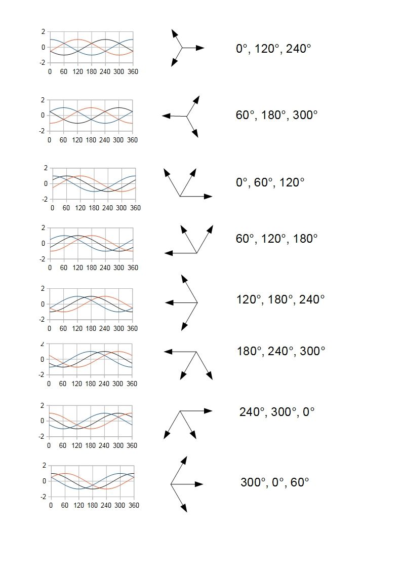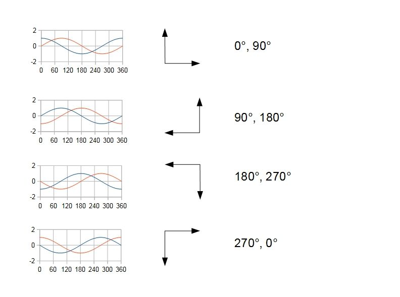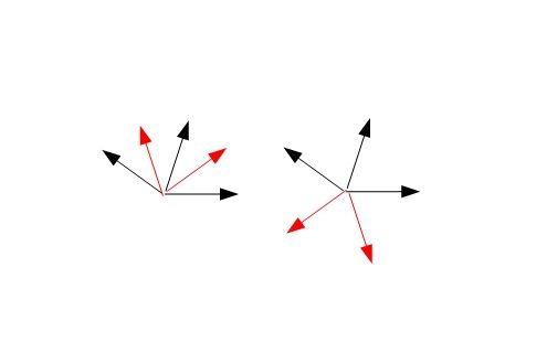

A two phase system has sources that differ by 180/2= 90(+/-180)degrees. A three phase system has 180/3=60(+/-180)degrees. The +/-180 is, as Chris said, invisible so for three phase we usually refer to the balanced 0 and+/-120 phases from 60-180=-120 and -60+180=120.Originally Posted by Art Mann

Three phase systems are used for power transmission because the symmetry optimizes transmission costs. Two phase is used for things like stepper motors.
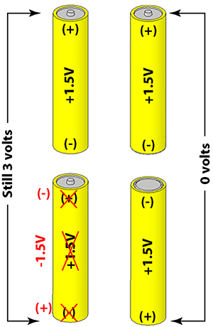
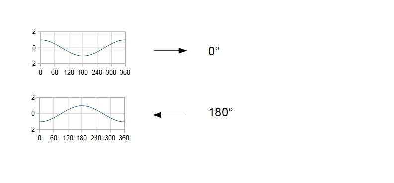
Why is the 180degree difference hidden? Imagine having a phase meter. If you measure the phase of an ac signal between two wires as 0degrees you can then reverse the measurement probes and read 180degrees. The act of reversing the probes has not created a new phase, it merely shows the difference in reference points.

 Reply With Quote