Page 1 of 2 12 LastLast
Results 1 to 15 of 22

Thread: Yet Another Smoother

  1. #1

    Yet Another Smoother

    Dave Weaver's recent threads on his cocobolo smoothers motivated me to get cracking on a plane I've been planning. I made a little smoother last year (also cocobolo, with a 1 1/4" iron) that is just about my favorite plane, so I want to make a slightly larger brother. I have a 1 3/4" vintage Buck double iron that I bought at PATINA for $10, and a dry block of goncalo alves that I'm anxious to use, so I might as well do it.
    I'm not going to do anything like an exhaustive thread; it's completely unnecessary at this point. I'll just show a few progress pics along the way. Some of my methods are different than Dave's, so that might be slightly interesting to some.

    To start, here's the basic geometry I'm planning.

    photo-148.jpg

    It's a little confusing to look at because of the way the lines extend. The important thing is to look at the only vertical line--that's the wear. I'm making this one 90°. The line that intersects the wear from the right determines how tall the wear is (about 1/2"). The line that intersects it from the left is for the abutments. To make the abutments properly--which is what Dave, Kees, and I have been talking about over 3 or 4 threads for the past couple months--they have to terminate in the middle of the wear.
    After I lay out one side, I transfer my lines across both top and bottom with a square, then mark the other side. Then I cut the mortise. For the finish cuts, I like to use a guide--just a piece of scrap with the correct angle cut on one end.
    Anyway, here's the mortise chopped out.

    photo-138.jpg

    The goncalo alves looks very nice, particularly on the tangential plane, and it chops much more easily than cocobolo or jatoba (the nastiest wood I've used in planes). I can see why planemakers like Phil Edwards use it so much.

    Before making the saw cuts for the abutments, I decided to do a little side project and make a new abutment saw. In the past, I've used a repurposed drywall saw. It works, but I wanted to upgrade a little. I recently got a box of vintage compass saw blades, 14" long and .060 thick, perfect for what I want. The blades come with an obscene amount of set, so I squeezed them in a vise, then jointed the teeth down to little nubs, and finally flattened both sides on some sandpaper. I cut the blade down a little so I'd have 7" of teeth. Last, I sharpened it and made a simple handle.

    photo-152.jpg

    Why go to the trouble of making a saw (besides that I like to make tools)? I think it will make sense after you see the cuts.

    photo-140.jpg

    Here you can see the cuts for (left to right) the bed, the abutments, and the front ramp. The bed is just a through-cut, 1/4" deep. The front ramp is also a through cut, but angled; it's 1/4" deep at the top and zero at the bottom.
    The tricky cut is the abutments. It's a stopped cut, and the closer you can get to full depth at the bottom, the better. With the thick .060 blade and the saw filed for a push cut, you can really get aggressive, lead with the front tooth, and cut to the proper depth. A floppy japanese flush saw won't do this. If I didn't have this saw, the next best tool is an edge float.
    I use a spacer block to make the cut for the abutments. I spray a little Spray 77 on it and stick it to the bed. It pops off easily with a mallet and the glue comes right off with mineral spirits.
    Oh by the way, the homemade saw works like a dream. And yes, that is an ugly stray chisel divot on the left side. It may come out later; if not, I'll live with it. Bummer though.

    The next thing is to knock out the waste, chisel everything as smoothly as possible, then finish up with floats. If you don't want to buy or make floats, you can use small vixen files, which can be found for less than $10 on the bay, or you can even cut wooden wedges to size and glue on some sandpaper.

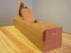
    Here's the last pic for today.

    photo-141.jpg

    This shows my favorite technique for fitting the abutments. Take a piece of 1/4" scrap and make a wedge of the proper angle (mine is 10°). The first thing obviously is to make sure that the angle is correct. Once you're done with one side, make a pencil mark flush at the top of the plane. Then work the other side. If you look closely, you can see the pencil mark is about a 32nd high, so I've got a little more to do. You can match the two sides to a pretty phenomenal degree of accuracy this way.
    Just below the bottom of the wedge, you can see I've trimmed the abutment so that it intersects nicely with the top of the wear. It's an awfully small thing to make such a big deal out of, but it is so much cleaner than any other way of doing this. I never saw this detail until Dave started showing pictures of some of his vintage planes.

    More in a day or two, hopefully.
    Last edited by Steve Voigt; 07-06-2014 at 11:04 PM.

  2. #2
    I never thought to cut the escapement to release things. That would've saved a lot of sweat!

    Your work is much neater than mine, too.

  3. #3
    Join Date
    Jan 2009
    Location
    Williamsburg,Va.
    Posts
    12,402
    Yes,a very neat looking job!!

  4. #4
    Join Date
    Aug 2013
    Location
    Princeton, NJ
    Posts
    7,296
    Blog Entries
    7
    Gorgeous work Steve!
    Bumbling forward into the unknown.

  5. #5
    George, Dave, and Brian, thanks!
    David, speaking of sawing, I forgot to mention something. Making the mortise for the chipbreaker screw, I never would have thought of sawing the sides, but I saw that in your thread and decided to borrow it. Worked great!

  6. #6
    Good job so far , Steve! very neat.

    At the moment I am moving my entire workshop from the graden shed to the garage and moving all the junk from the garage to the shed. I hope to be finished before the summer hollidays, but I am scheduled for some orthopedic surgery after that. So, while I'm very eager to give it a try too, I'll have to wait.

    While browsing around I found these sketches on Caleb James' website. They show the little triangle too, but because this is a single iron plane, the frontline of the abutments goes through the mouth, doesn't end in the wear, so it is much easier to make.

    http://kapeldesigns.blogspot.nl/2013...wedge-for.html

    Wooden+plane+mouth+wedge+abutment+view+cut+way+half.jpg

  7. #7
    Thanks Kees. I hope your shop move is an upgrade!
    I like Caleb's blog a lot. The shape of his smoother, which I think is based pretty closely on the Old Street model, is my favorite version of the coffin shape.
    I have only found one other picture of the "triangle" outside of SMC. This is from Paul Seller's blog:

    DSC_0185.jpg

    It's a silly pic, with the artfully arranged shavings (plane porn?), but the woodie in the foreground is instructive. You can just barely see the left side of the top of the wear. I like the way the cut of the abutment is not horizontal, but rises up at an angle; this makes the taper more gradual. The eyes and the wedge are nice too.

  8. #8
    Join Date
    Aug 2010
    Location
    USA
    Posts
    5,582
    Quote Originally Posted by Steve Voigt View Post
    To start, here's the basic geometry I'm planning.

    photo-148.jpg

    ...The important thing is to look at the only vertical line--that's the wear. I'm making this one 90°. The line that intersects the wear from the right determines how tall the wear is (about 1/2").

    photo-141.jpg


    Just below the bottom of the wedge, you can see I've trimmed the abutment so that it intersects nicely with the top of the wear. It's an awfully small thing to make such a big deal out of, but it is so much cleaner than any other way of doing this. .
    First off - thanks for the detailed description and pictures. This coupled with Dave's previous thread are very informative. You are doing fine work

    I do have a couple questions though related to the actual purpose / function of the wear:
    1) why are you making the wear so tall? 1/2" seems about double what you really need for this feature,
    2) if you expect to need 1/2" for the wear then why go with a 90 deg wear angle? - it seems it should actually taper to be more parallel with the blade itself. This is actually what the Caleb James images show also. See figure 8 http://kapeldesigns.blogspot.nl/2013...wedge-for.html

    My questions come about from all these detailed discussions because after all this, I see the 'wear' as the provision being made for future wear and re-dress of the sole. Having it thick enough so that you can prolong the life of the tool without significantly altering the throat characteristics. I can't imagine the need to allow for 1/2" of wear on the sole of this plane. Lets say you ultimately get 1/4" of thickness reduction after years of use and re-dress - at this point the throat opening in the bottom of the plane will have significantly grown in dimension, probably less important with a double blade plane. If the 'wear' were angled back to be more parallel to the blade then the the resultant opening size would be reduced compared to the 90 degree 'wear' angle.

  9. #9
    The cap iron is going to present a chip at 90 degrees or a little more vs. the sole of the plane. It's not going to slip up the iron like it would in a single iron plane. If you tried to make the wear too tight, the chips coming off of the cap iron would run into the wear and make a clog instead of running adjacent to the wear more or less and coming out of the plane.

    You also can't have the wear too low or your abutments will terminate in the escapement, which will be ugly.

    Also, having a taller wear allows the escapement to be a little less large, which is visually a little more satisfying.

  10. #10
    Quote Originally Posted by Pat Barry View Post
    First off - thanks for the detailed description and pictures. This coupled with Dave's previous thread are very informative. You are doing fine work

    I do have a couple questions though related to the actual purpose / function of the wear:
    1) why are you making the wear so tall? 1/2" seems about double what you really need for this feature,
    2) if you expect to need 1/2" for the wear then why go with a 90 deg wear angle? - it seems it should actually taper to be more parallel with the blade itself. This is actually what the Caleb James images show also. See figure 8 http://kapeldesigns.blogspot.nl/2013...wedge-for.html
    Thanks Pat, and good questions. I think David answered them, but I'll just add a little.
    The wear in a single iron is usually around 70°--roughly 25° steeper than the bed. Caleb's plane is a single iron. But the wear in a double iron has to be closer to vertical, for all the reasons David mentioned. Kees has actually done the measurements on this and has mentioned that double iron wears are usually between 80 and 90. Apparently the double iron planes in the Seaton chest are at 87° or thereabouts. So, 90° is at the top end, but in the range. On a purely practical level, I've had problems with wears in the 80° range, so this is just an effort to combat those problems.
    As to the exact height of the wear, I think I'll be able to say a little more about that soon, but Dave covered why it has to be taller.

  11. #11
    Join Date
    Dec 2011
    Location
    Israel
    Posts
    1,503
    Blog Entries
    1
    I think it's worth considering that the angle at the tip of the chip breaker will be a factor hinow steep you can make the wear.
    I make the wear on all my bench planes at 85 degrees, about 3\8 - 1\2 inch tall using hock irons which have fairly steep chip breakers. the setup is great, and actually works better than
    a single iron with the same set-up because the wear combined with the chip breaker send the savings straight up and out of the plane better than previous set-ups I've tried.

  12. #12
    I got through the next phase of construction, and it went well. The game plan was to make a wedge, flatten the bottom reasonably well, and test the plane. I want to be sure the thing actually works before I start cutting curves, chamfers, and all that jazz.
    I don't have any nice goncalo left for the wedge, so I'll use a piece of tropical mystery pallet wood. It's actually pretty nice wood: hard, dense, and stable. I've had it for years, so I know it's dry.
    Dave gave me some good ideas for improving how I make and fit the wedge. I didn't do it exactly like he did, but close.
    First, I measured the opening of the plane at the top and bottom. I have 1.79" at the bottom and 1.80" at the top, so I squared up the wedge stick at 1.795. I laid out an 11° taper on both sides (10° plus 1° for the taper of the double iron) and then saw and plane pretty close to the lines. Here's the planing setup:

    photo-143.jpg

    I push the thing halfway down the throat to see if I'm on the right track, and I am. So then I plane to the lines and cut out the fingers to approximate size. This gives me enough flex that I can insert the wedge all the way. Now it's just plane and check until I'm satisfied. Here's the wedge almost done:

    photo-144.jpg

    When happy, I cut the thing to length, trim the fingers, and start testing the plane.
    The plane doesn't work perfectly at first. I have two problems. First, when I tap the blade, the blade tilts to the right, cutting deeper on that side. This problem is easily fixed: I plane a single shaving off the left finger, and it works as it should.
    The second problem is more interesting. The plane clogs on one side. I mentioned before that one abutment was better looking than the other; the first was cut back a little more than I intended. But the one that looks great is clogging, so I have to cut it back some more. Here it is after re-cutting:

    photo-154.jpg

    Hopefully you can see that the cut is about 1/32" above the top of the wear. It doesn't look bad; I'm perfectly happy with it. But next time, I will do it right.
    So, this goes back directly to the question Pat asked today: How tall should the wear be? Right now, it is about 15/32, and that is just barely too small. So, I would say 1/2" is the absolute minimum, but 9/16 or 5/8 would be better.
    By the way, the term "triangle" has been used a bunch, so I think I should mention that I completely remove the tips of the triangle, then pare. So it's really more like a trapezoid.
    OK, enough blathering about geometry. Once the abutment is fixed, I get this, and I'm stoked.

    photo-145.jpg

    Vertical shavings, about .008 thick. I didn't arrange the shavings--that's just how they came out of the plane. It's only SYP, which is soft, but can produce more problems with clogging than other less resinous woods. So I'm pretty pleased.

    Probably can't see in the picture, but the surface of the board has a lovely, shimmering quality. There are tracks, so I need to work on the corners of my iron, but that's no problem.

    photo-146.jpg

    I planed some elm seat blanks also:

    photo-147.jpg

    The elm is weird; even on the tangential plane, the shavings fall apart the way QS oak does. Doesn't matter what plane I use. But the upshot is that the plane works, and doesn't clog or tear out, so tomorrow I can move on to shaping. I'll try to plane some more macho wood before this thread is done.

    Edit: I forgot to mention--the mouth on this plane is somewhere between .030" and .040", or just under 1 millimeter. I have absolutely no desire to make a tighter mouth than this; it works great.
    Last edited by Steve Voigt; 07-08-2014 at 1:50 AM.

  13. #13
    You should test with some fluffy shavings in the 1 thou range too. These are the most suspectible to clog.

    Otherwise I can see why you are pleased. Pushing the plane with such sharp corners can be quite entertaining, doesn't it?

  14. #14
    Join Date
    Dec 2010
    Location
    South Coastal Massachusetts
    Posts
    6,824
    I think you should make two of everything, so I don't have to beg for one when you're finished.

    Your "mini-smoother" defines excellence among my planes, and I've got some from established makers.

    The main difference I'm seeing between current offerings of this type, and vintage planes is that
    the vintage planes have worn parts and resulting alignment problems.

    I wonder if the old planes ever performed so well, and if time on the bench makes them loose?

  15. #15
    Quote Originally Posted by Jim Matthews View Post
    I think you should make two of everything, so I don't have to beg for one when you're finished.

    Your "mini-smoother" defines excellence among my planes, and I've got some from established makers.

    The main difference I'm seeing between current offerings of this type, and vintage planes is that
    the vintage planes have worn parts and resulting alignment problems.

    I wonder if the old planes ever performed so well, and if time on the bench makes them loose?
    Jim, that's very kind of you; I'm glad that plane is working out.
    Regarding old planes, I think the answer is that some of them worked fantastically, and still do; the problem is getting a good one.
    As part of this whole abutment discussion, I was hoping to post some pictures of poorly cut planes, for comparison. I took some pics in an antique shop this weekend, but unfortunately the lighting was bad and none of them are worth posting. But it was really instructive to look at these planes, knowing what I know now. It was clear that the throats, abutments, etc. were designed to be cut quickly, probably with mass production setups, and the priority was volume rather than quality.
    On the other hand, Dave has shown a number of old planes that were obviously very well made. The trick is separating the two.

Posting Permissions

  • You may not post new threads
  • You may not post replies
  • You may not post attachments
  • You may not edit your posts
  •