Page 4 of 9 FirstFirst 12345678 ... LastLast
Results 46 to 60 of 123

Thread: Lingerie Chest started and your strategy wanted

  1. #46
    Join Date
    Feb 2004
    Location
    Perth, Australia
    Posts
    9,494

    One step back

    It's always a bit disheartening to hit a problem that threatens to derail the project before it has managed to truly get underway.


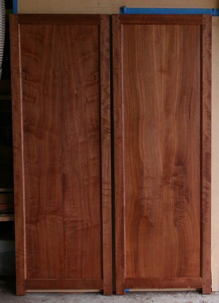
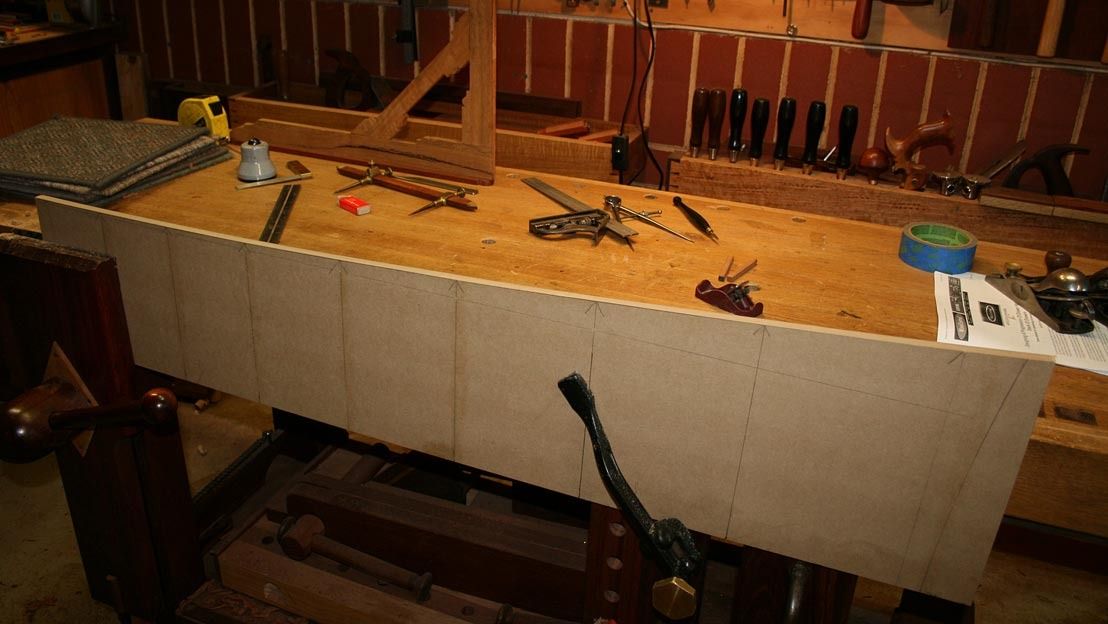
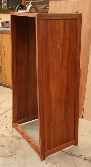
    When we left off last time, the panels were done and I began planning the drawer dividers.


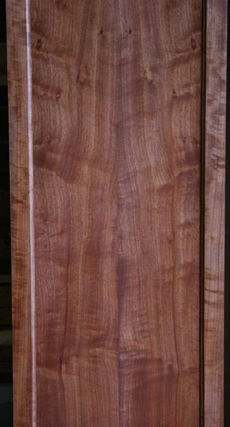
    Then I noticed that the join in the book-matched panel on the left had split in near the centre. It was possible to flex it back-and-forth. The lower- and upper sections were still holding. I wiggled a little hide glue into the split and pulled it tight with clamps. I returned after a day, and it looked strong. It had been my plan all along to add 1/4" thick strips at the inside of the panel, which would both stiffen and reinforce. Now it looked like this would be necessary, rather than insurance.


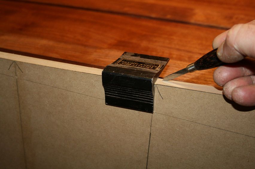
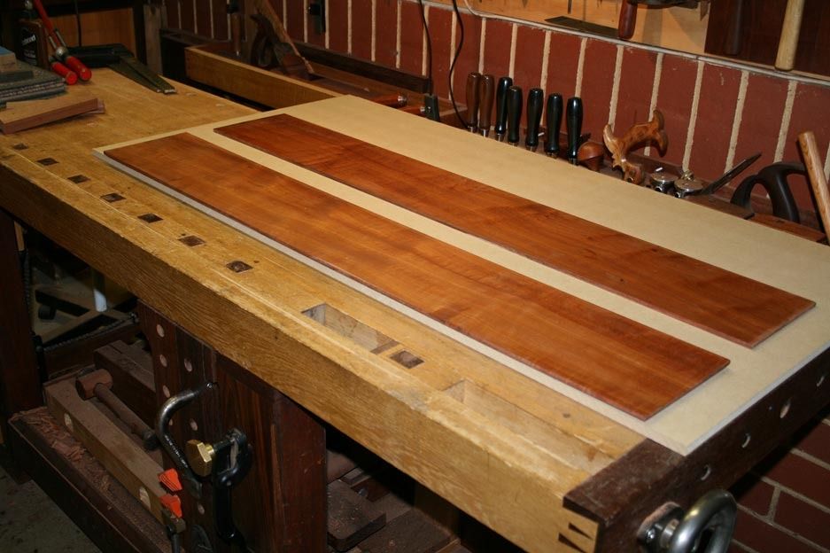
    The areas for the 3" wide strips were marked off, and the finish scraped off the centre of each panel. One panel remained intact as this work took place. The other split .. again. Damn and bugger.


    My wife said "take it off". I thought I may be getting lucky, but - no - she meant the panel


    Thank goodness for hide glue! I had used Titebond Liquid Hide Glue all along. However, I have never had to undo anything before. This was a first.


    The first step was to drill out the pins. One side of the hole was covered with waterproof tape and boiling water was poured in. A heat gun added more heat. A clamp was used in reverse direct to push the sections apart. Slowly it moved, and then .... then my camera decided to blow up the memory card, and every photo of this process was lost! Double damn!


    I started over today ...


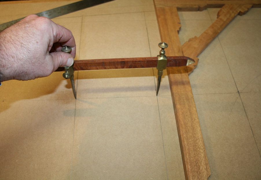
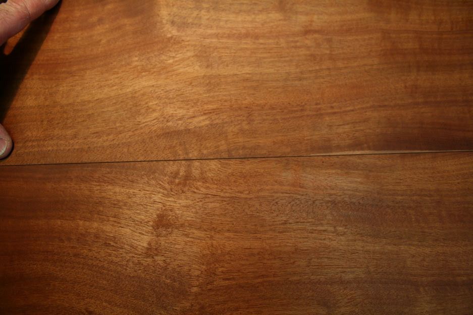
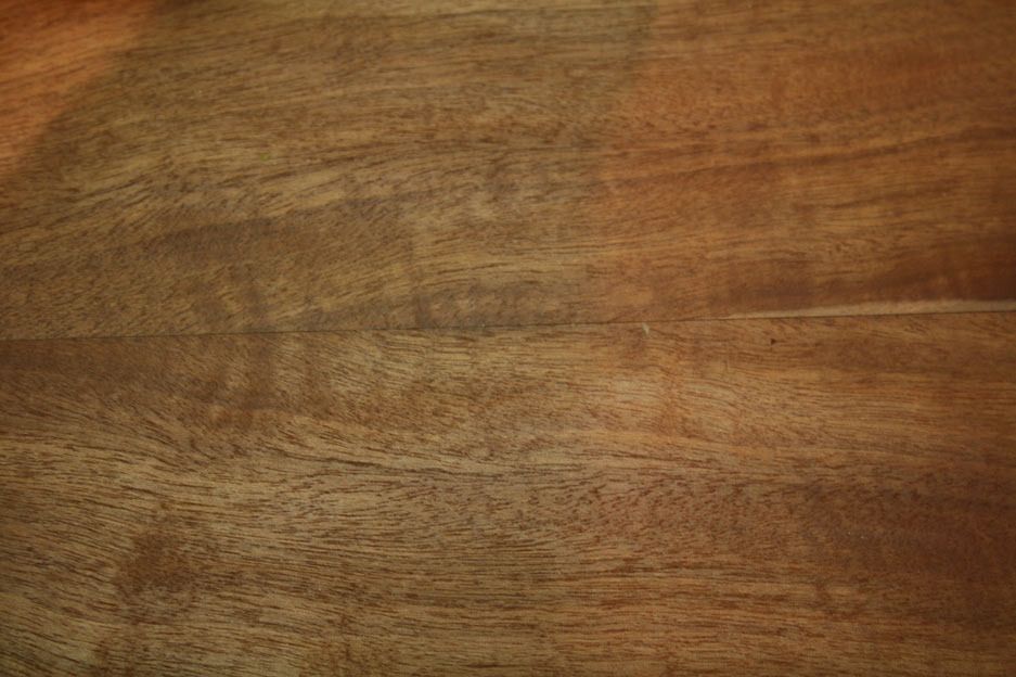
    Post-mortum of the panel indicated that the spring joint gap was too large ...


    Clamping the pieces together would have squeezed out the glue.


    Checking the sides against a straight edge, it was clear which piece was the offender ..


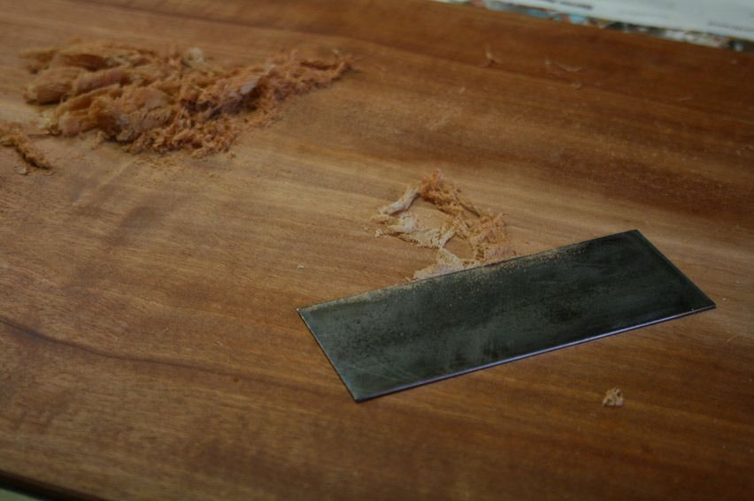
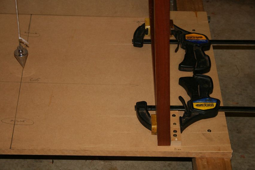
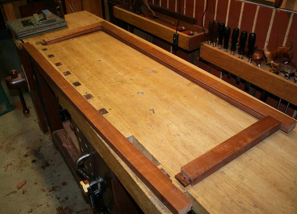
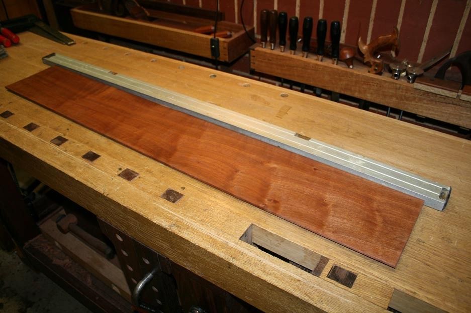
    I am not sure if I demonstrated the method I used to joint these thin 1/4" thick panel sections. Well this is how it was done ..


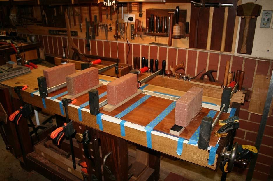
    First step was to lift the board up on a 1/2" thick section of MDF (nice and flat). The second piece was added for balance ...


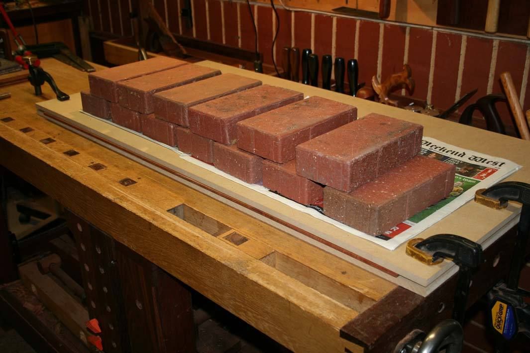
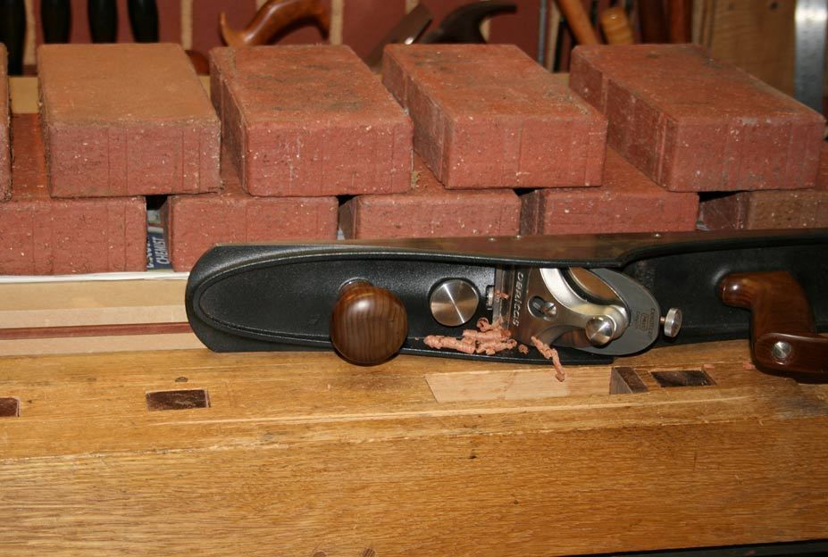
    A second piece of MDF was layed on top, and then weighted down with bricks (to ensure the edge was flat and parallel to the bench top ..


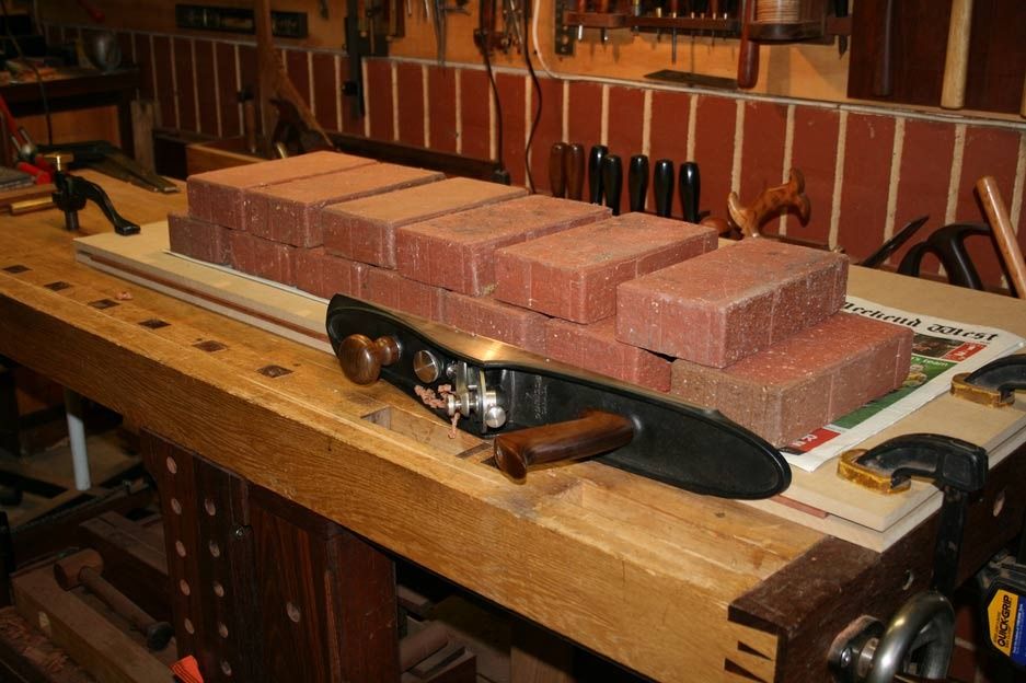
    A jointer plane was now about to shoot the edge square ..


    Generally I plane the centre to create a spring joint, but here I was reducing the existing gap by planing it flatter. In the end it was a very slight, almost imperceptible hollow ..


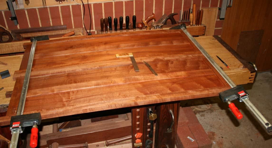
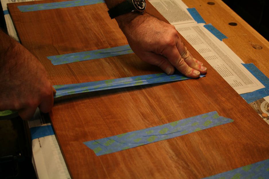
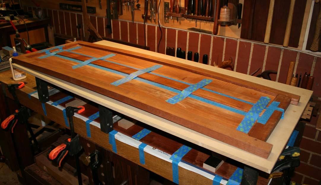
    To glue up, the panel pieces were first work from the back side. Tape was stretched across and used to pull the sections together ..


    The full side was done, with the joint line reinforced to minimise glue running out ...


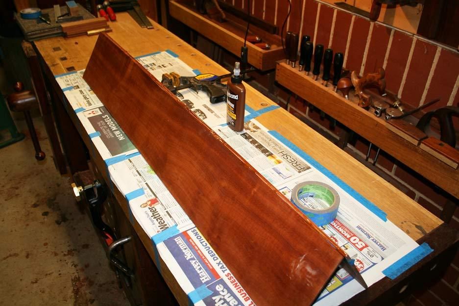
    Reversing the panel, glue was spread down the join ..


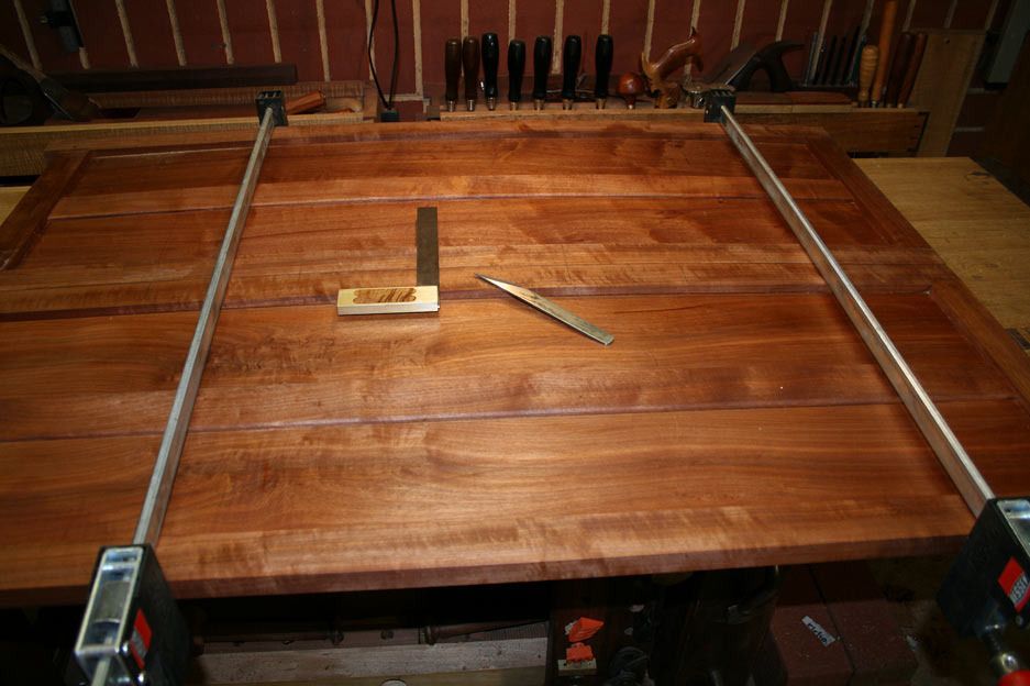
    This could then be opened out, taped together (again with stretched tape), joins levelled with a plastic mallet, and lightly clamped together. Bricks were added to hold everything flat while the glue dried ...


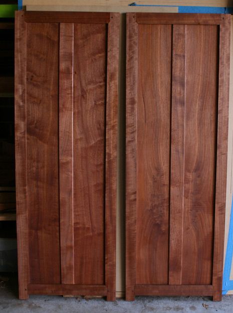
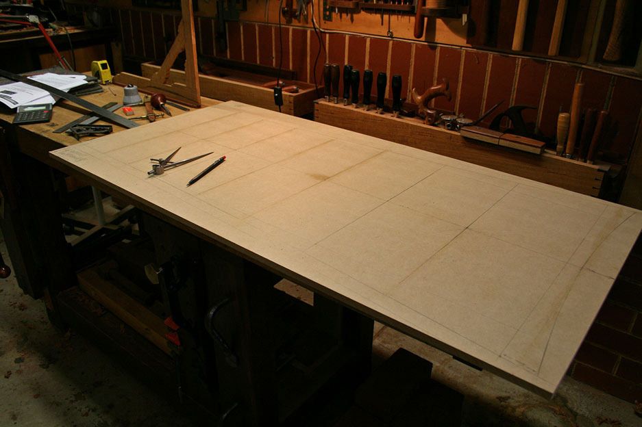
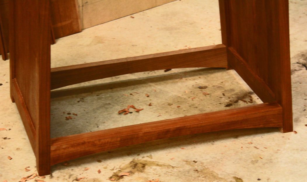
    While this is drying, the solid panel received its reinforcing strip ...


    The program will be resumed shortly ...


    Regards from Perth


    Derek

  2. #47
    Join Date
    Aug 2013
    Location
    Princeton, NJ
    Posts
    7,298
    Blog Entries
    7
    That's aggravating, but glad to hear you were able to repair without destroying the frame.
    Bumbling forward into the unknown.

  3. #48
    Join Date
    Aug 2012
    Location
    Missouri
    Posts
    2,152
    Great recovery Derek. Those things happen to everyone, it's what one does to fix the problem that matters. Band aide or permanent always chases us around. Happy to see you went with permanent even though it was a lot of work. Band aides can get pretty nasty after they start getting old. Very nice of you to show the work instead of just going on like it didn't happen.
    Jim

  4. #49
    Join Date
    Aug 2009
    Location
    'over here' - Ireland
    Posts
    2,532
    Hi Derek. Frustrating that sort of thing. Apart from joint configuration adhesives always have the potential to throw up a problem like that out of the blue - all it takes is a hint of something on the surface that reduces the wetting effect, or the penetration/mechanical interlock. Along with dispensing and handling complications it's one of the major factors that tends to inhibit further update of adhesives use in industry - especially on structural/mission critical stuff.

    Watch out for the bricks. I've been known to use them as i have a handy stack from when we built the house years ago - but they can be very prone to dropping grit which can easily get embedded in wooden surfaces - with potential for damage to both work and tools.

  5. #50
    Join Date
    Feb 2004
    Location
    Perth, Australia
    Posts
    9,494

    Back on Track

    First of all I am very pleased - and relieved - to mention that the panels are back in one piece and together.


    Then just a couple of comments about the failure and the hide glue ...


    The reason for the failure was that the join was glue-starved. As simple as that. Well, almost.


    The reason for the join being glue starved was not because I used too little glue, and not because of the type of glue, but because I over-tightened the clamps.


    The over-tightening was due to the spring joint being too wide. What is a good- and what is a bad spring joint? Well, a good joint is one that may be closed with hand pressure, and a bad one is one that requires help to do so. In the case of the one panel, I got it right. In the case of the failed panel, clearly I did not. I could see light through the centre when I inspected the join, and immediately I knew this was the cause. Pulling the join together with a clamp just disguised the issue since all the tension was at the centre (where the join failed), and the force squeezed the glue out ...... no glue + tension = open up.


    A second question is "why spring at all". Some like to do this and others argue that it is not necessary, that glue is tougher than wood. In my book, it is important to ensure that the ends of a panel contact each other. If there is any curvature to mating sides (and often this is difficult to see - which is the point), extra clamping at the ends creates two tension sections .. where as the spring joint only creates one tension point. But the spring must be almost imperceptible, as in the photo I posted.


    A third issue is the choice of Titebond hide glue. Well hide glue rocks ... but Titebond? I have had a number of emails warning me about its use, that it is unreliable, etc. My experience with it is not long - about two years. In that time I cannot recall a failure. It needs to be pointed out that the mortice-and-tenon joints were solid. There was no failure there. Still, I accept that some of these critics are experienced with hide glues.


    I must admit that I have avoided going to the trouble of preparing the stuff myself since I am lazy. The issue is that I get into the workshop on weekends only, and making up a fresh batch of glue each time, keeping it warm, etc .. well, it does not thrill me. Anyone have a way of circumventing this?


    So back to the repair.


    It the face needed a minimal amount of scraping to level the joint ...


    ... before I called it good and re-glued and pinned the panel inside the frame.


    The repaired panel is on the left ...


    Reinforcing strips were added to the rear - I had planned to do this anyway to beef up the thin panels. They will not be seen (on the inside) but will offer a little more reliability ..


    Some may be interested in the supports I built to aid accuracy in dimension and to keep everything square. The first was the base, which also will enable the chest to be moved around later ..


    The other clamps across the top ..


    So now we are back to clamping all on the jigs, with an added section of MDF clamped to the rear. The plumb bob ensures that vertical and centre is created, and may be returned to at any time ...


    Once this is done, the inside perimeter can be traced onto the MDF. The MBF is moved to the bench, where the drawer dividers are drawn in. This is to act as a template.


    A line is drawn down the centre of the cabinet template, and the dimensions first marked on this centre line ...


    They are then transferred to each side ..


    Here is the template back supporting the chest sides ...


    I moved it to the other side and it was reassuring that there was about 1mm difference in the marked outline.

  6. #51
    Join Date
    Feb 2004
    Location
    Perth, Australia
    Posts
    9,494
    Now the intention was not to use these marks as the template, but rather to create a template from them. To do this the MDF outline was sawn down the centre, and then the curved side band sawn out, with a little cleaning up done with a small block plane.


    Measurements are marked both sides ..


    ... and then transferred to each side of one board (only) ..


    The panels are clamped together and the markings transferred from one board to the other ..


    Once one side is match, the boards are rotated to complete the other matching edges ...


    Now we can move on to marking out angled sliding dovetails and build the draw dividers.


    Regards from Perth


    Derek

  7. #52
    Join Date
    Aug 2013
    Location
    Princeton, NJ
    Posts
    7,298
    Blog Entries
    7
    Derek,

    Are you tapering the sliding DT's on the sides? I left mine plain out of fear that a long tapered DT with grain going opposite directions would lead to a crack, but maybe that is unfounded.

    Cheers
    Brian
    Bumbling forward into the unknown.

  8. #53
    Join Date
    Feb 2004
    Location
    Perth, Australia
    Posts
    9,494
    Hi Brian

    The sliding dovetails will be very short - just about 1/2 - 2/3 of the leg width each. Consequently they will not be tapered.

    What I have to do is fit the sliding dovetails into angled sides. I have a plan but any suggestions?

    Regards from Perth

    Derek

  9. #54
    Join Date
    Aug 2013
    Location
    Princeton, NJ
    Posts
    7,298
    Blog Entries
    7
    Ahh I see, I might want to cut an angled housing into the legs so that you can use straight on dovetails which will be much easier.

    How are you building your web frames? Separate pieces or making assemblies first?
    Last edited by Brian Holcombe; 06-21-2015 at 12:39 PM.
    Bumbling forward into the unknown.

  10. #55
    Join Date
    Feb 2004
    Location
    Perth, Australia
    Posts
    9,494
    Spot on with the housings, Brian.

    For the webs, I plan separate assemblies - to do the front and rear dovetailed sections first, then add in the mortice and tenon sides.

    Regards from Perth

    Derek

  11. #56
    Join Date
    Aug 2013
    Location
    Princeton, NJ
    Posts
    7,298
    Blog Entries
    7
    Cool, I think that'll do well. Looking forward to more updates, it's coming along very nicely.
    Bumbling forward into the unknown.

  12. #57
    Join Date
    Feb 2004
    Location
    Perth, Australia
    Posts
    9,494

    Before the drawer blades ..

    The cabinet carcase is now complete and together as a dry fit.


    You cannot see the curve on the front elevation in this photo, but it is clearer in the documentation ..


    It had been my intention to post the carcase with completed draw blades – this would have been the next stage in any cabinet with straight sides. However it became increasingly apparent that, as a result of the many curves, this build is a tad more complicated, and I am have been left wondering whether I would ever get to be in a position to build the drawer blades as something else kept cropping up! It was a case of “I’d better to this before I get to that as it will not be possible later. And on and on ..


    It is possible – and indeed I like to hear the opinion of others here – that the sliding dovetails for the drawer blades could be marked and formed from inside the completed carcase. I am now seriously considering this method. Indeed, I cannot see an alternative. The carcase could be dis-assembled and assembled repeatedly for work to be checked, carried out, and then checked again. However the latter will cause wear on the joinery, with resulting loss of tautness and accuracy.


    Let's hear your thoughts on constructing the drawer blades. The front and rear are planned to be sliding dovetails (as has so much of this construction so far).


    Here is the build in detail: http://www.inthewoodshop.com/Furnitu...werBlades.html


    Regards from Perth


    Derek

  13. #58
    Join Date
    Feb 2004
    Location
    Perth, Australia
    Posts
    9,494

    Moving Forward

    It seems like a lot of planning for little actual progress. However the basic carcase was glued up after stopped rebated were planed at the rear, and the strategy for making the sliding dovetails in the curved sides from inside the front leg/frame was finalised.


    http://www.inthewoodshop.com/Furnitu...ngForward.html


    Regards from Perth


    Derek

    p.s. anyone reading this stuff?

  14. #59
    Join Date
    Sep 2008
    Location
    N. Idaho
    Posts
    1,621
    Hello Derek,

    Yes! as always. Appreciate you taking time to post here at SMC as well as other sites.

    Thanks,
    C
    "You can observe a lot just by watching."
    --Yogi Berra

  15. #60
    Join Date
    Sep 2011
    Location
    Kelowna, BC, Canada
    Posts
    179
    Derek,

    It is far enough above my skill level that I merely observe and learn. But rest assured that you have at least one peson reading. Absolutely fascinating.

Posting Permissions

  • You may not post new threads
  • You may not post replies
  • You may not post attachments
  • You may not edit your posts
  •