Kees. You may find the following of interest in keeping the mouth opening tight.Originally Posted by Kees Heiden

Stewie;


 Member
Kees. You may find the following of interest in keeping the mouth opening tight.
Stewie;
Last edited by Stewie Simpson; 03-08-2016 at 9:11 PM.
Member
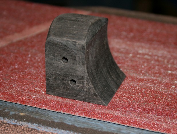
Taking a break from other project work I took some time out to test the 12* wedge making jig. Before being passed through the table saw the wedge stock was secured in place with double sided tape. Final dimensioning was completed using a traditional wooden smoothing plane. The solid packing template for kerfing the outer wedge abutments was also completed.

Last edited by Stewie Simpson; 03-13-2016 at 1:37 AM.
[OP]
Member
Yes it is pretty obvious when you think about it, raising the wear angle without opening the mouth.
 Contributor
I did essentially the same thing on an infill to increase flow while retaining a 60 degree bed.
Of course, I had to keep the hollow low as there was a 1/4" thick sole, which was also filed back from the vertical (I cannot recall the angle). I recall doing this with Stanley planes many years ago, having read one of David Charlesworth's articles in a magazine (before they were published in a book).
Regards from Perth
Derek
[OP]
Member
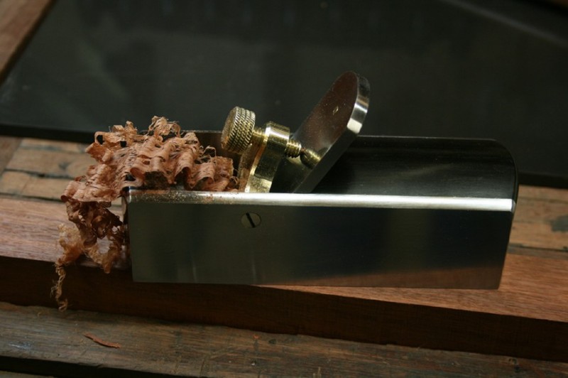
BTW, you don't really need a jig to cut a wedge
foto (7).jpg
Member
Kees. I plan to repeat the same wedge profile on some future woodies, so that jig is going to come in handy. I have a bad habit of planning ahead with my project work.
[OP]
Member
I was just kidding. I am now working on my last two bench planes, a try and a jointer. I don't think I need more then 5 bench planes.
Contributor
Doesn't the "jig" lie in the wrong direction to plane the wedge? Surely the wedge will slide out if you are planing with the grain? How else would you do this?
Regards from Perth
Derek
Member
Hi Derek. The grain direction on the top surface of the wedge is running left to right (as seen within the photo). Relying on the side grain view to indicate the direction of top surface grain can be misleading due to the unique shape of the wedge.
Stewie;
 Member
stewie,I am suspicious as to where this picture came from. It shows an incorrect representation of the sole of the plane. Unless there is also a contact area right in front of the iron,this plane will soon be generating a convex surface on the wood it cuts. Just like a compass plane. I know who thinks this is correct as drawn,but it is not.
Also,since the angle that the iron rests upon will also be worn back as the sole wears,or is dressed repeatedly,the mouth will still be opened anyway,it seems to me. Maybe I am wrong? Dunno,late night,headache this A.M.!New pain meds are not pleasant. But I am not wrong about the needed configuration of the sole to have 3 contact points.
Last edited by george wilson; 03-13-2016 at 9:59 AM.
Contributor
I think you are right, George. The plane (kanna) should be touching at three points - heel, mouth and toe. This is only touching at the heel and toe. Poor drawing?
Regards from Perth
Derek
 Contributor
The deficiencies of that drawing were pointed out here as well;
http://thecarpentryway.blogspot.com/...-and-wave.html
Bumbling forward into the unknown.
Member
As I said,I'm suspicious of who made that drawing. If it is him,apparently he still does not understand how his specialty area,which includes Japanese planes,work. Or else it is an old drawing. Even the acknowledged master, Odate, shows a 3 point contact area on the soles of Japanese planes in diagrams in his book. At least in the book I SAW! (The link above shows only 2 points of contact.) Though I don't use Japanese planes(my back won't allow it),I,or anyone with a REASONABLE grasp of mechanics,can easily see that the 3rd. contact area,right in front of the throat,is needed,to keep the plane from becoming a compass plane.
Of course,that issue is not the subject under discussion here.
Last edited by george wilson; 03-13-2016 at 11:10 AM.
Contributor
George, he points out the drawing as being incorrect for a truing plane and mentions exactly what you did, which is that the two outside points and long hollow make a compass plane.
Bumbling forward into the unknown.
Member
The 1st stage of mortising out of the escarpment has commenced; from the blade bed to the wear line, working along the inside abutment lines. In effect forming 4 flat surfaces; front, back, and the 2 side walls that separate them.
The assortment of hand tools I am using. Right side of the planemaker floats is a Logier Sapphire Coated Luthier Rasp. Cut #11 on 1 face; Cut # 13 on the opposing face. Its the 1st opportunity I have had to use this rasp since I purchased it 12 months ago fro planemaking work. Its quite aggressive, but it leaves reasonably a smooth finish to the surface of the wood. Ideal for the flat bed surfaces you need to create when working on traditional wooden bench planes. Next to the Logier Rasp are 2 chalking templates I used to level off the flat surfaces formed after mortising. At a later stage the chalking technique will again be used to achieve a precise fit of the wooden wedge within its abutments.
imo, if you don't possess the correct temperament within your work, its best to avoid traditionally mortised out wooden bench planes. Steve Voigt and Kees may wish to add their own comment.

Last edited by Stewie Simpson; 03-15-2016 at 2:46 AM.
 Posting Permissions

 Reply With Quote