Page 2 of 2 FirstFirst 12
Results 16 to 24 of 24

Thread: Perplexing dust collection enhancement fail

  1. #16
    Join Date
    Mar 2007
    Location
    Kingston, ON, Canada
    Posts
    223
    I'm in Kevin's camp. If the dust is being adequately picked up, then it's a winner!

    I should mention that I, too have a Felder K700 series saw (the K700S, to be exact) and have also produced my own after-market above blade set-up. Like Joe, I started with the stock blade guard, but in my case I merely epoxied into place a bushing made from a short piece of 2 1/2" plumbing drain to enable me to mate the guard to a 3" flex hose. Yep, I only have a 3" flex hose acting as my above-blade dust collector, and I'm very impressed with how dramatically it's improved things. Is it perfect and does it pick up all the dust? Not by any stretch of the imagineation, but then it's met my objectives of removing the vast majority of the above-blade dust, while allowing me to retain the narrow profile the stock guard provides. The only thing I think I'd consider adding would be one of those broom, or whisker sets to the sides of the guard which would close up the gap more effectively.

    I should mention that I don't have anything other than my Mark 1 eyeball to tell me how effective the new arrangement is. I'm happy.

    Here's a few photos of what it now looks like:

    Above blade photo.jpg

    Above blad1 photo 1.jpg
    Marty Schlosser
    Kingston, ON, Canada
    Instagram: https://www.instagram.com/apexwoodworks/
    Facebook: https://www.facebook.com/ApexWoodworksFurniture/
    YouTube: https://www.youtube.com/channel/UCkmbvXb44CJ9t17SbHEWxJg/videos

  2. #17
    Join Date
    Apr 2006
    Location
    Phoenix AZ Area
    Posts
    2,505
    Quote Originally Posted by Kevin Jenness View Post
    Does it pick up the dust adequately?
    Yes it does

  3. #18
    Join Date
    Apr 2006
    Location
    Phoenix AZ Area
    Posts
    2,505
    Quote Originally Posted by David Kumm View Post
    Joe, are you measuring just the guard cfm or is the bottom saw port open too? Your mod would show more improvement with a traditional collector than a smart providing the smart had speeded up to reach its designed airflow with the small port. Dave
    I am measuring with the port to the bottom of the saw open too. In my setup both gates open automatically when I start the saw.

  4. #19
    Quote Originally Posted by Joe Jensen View Post
    measured approx. 6970 ft per min with both blade guard assemblies....... I can't see why the CFM did not change even though I almost doubled the cross sectional area of the port on the guard.
    I might be totally off, here, but aren't we talking about two different things: velocity of the air (feet per minute - a measure of speed), and CFM (cubic feet per minute - a measure of volume)?

    Restricting the size of the duct will increase the velocity, but decrease the volume of air moved.

    Higher velocity air might be better to capture wood chips which are flying off the blade with a lot of speed, already. Higher CFM will move more suspended (stationary) dust, but won't grab "chunks" from as far away as as a higher velocity airstream.

    So, here's my hypothesis (go ahead and chew it apart, everyone ) - for capturing larger chips coming off a tool with higher velocity, it might be better to use less CFM to get more velocity. Although the optimal solution would be to arrest the chips' speed with some sort of mechanical barrier, then suck them up with tons of CFM.

  5. #20
    Join Date
    Apr 2006
    Location
    Phoenix AZ Area
    Posts
    2,505
    Quote Originally Posted by Dan Friedrichs View Post
    I might be totally off, here, but aren't we talking about two different things: velocity of the air (feet per minute - a measure of speed), and CFM (cubic feet per minute - a measure of volume)?

    Restricting the size of the duct will increase the velocity, but decrease the volume of air moved.

    Higher velocity air might be better to capture wood chips which are flying off the blade with a lot of speed, already. Higher CFM will move more suspended (stationary) dust, but won't grab "chunks" from as far away as as a higher velocity airstream.

    So, here's my hypothesis (go ahead and chew it apart, everyone ) - for capturing larger chips coming off a tool with higher velocity, it might be better to use less CFM to get more velocity. Although the optimal solution would be to arrest the chips' speed with some sort of mechanical barrier, then suck them up with tons of CFM.
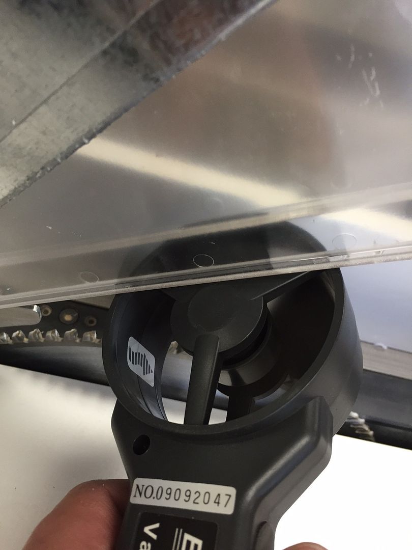
    I measured velocity and calculated CFM by knowing the cross sectional area where I measured. I don't know how you would measure volume. Everything I have read shows to measure velocity and calculate volume. I measured before and after two different places. First I put the anemometer which is about 3" in diameter at the base of the guard.

    Here is a pic of that approach. I found that the velocity was highest closest to the inlet and the highest I could measure with the new guard was 2150 ft/min and with the old guard 2030 ft/min.


    The other way I measured was to put the anemometer between the 3" flex duct and the 3" port on the guards. With that measurement I got about the same on both, 6975 ft/min.

  6. #21
    Join Date
    Feb 2013
    Location
    Tippecanoe County, IN
    Posts
    836
    Quote Originally Posted by Joe Jensen View Post
    .... anemometer which is about 3" in diameter ......put the anemometer between the 3" flex duct and the 3" port on the guards. With that measurement I got about the same on both, 6975 ft/min.
    I think it may be the measurement technique itself that's causing the odd results. The problem is that the anemometer has an effect on the flow. It's clear from just looking at it that the anemometer housing is an obstruction and reduces the effective area of the duct.

    Most of the time this type of measurement involves a duct that is larger than the anemometer and the main effect is to cause the velocity reading to be higher than without the anemometer in place. This effect is documented in a US Bureau of Mines report.

    In your situation I think something else is happening. Not only is there an area reduction but also a friction loss increase that's larger than you would expect based on area alone. That is, the cross section perpendicular to flow is not an open circle and so has more resistance than a circle of the same area. In addition, even though they are spinning, the vanes also cause a pressure loss.

    It's possible that with a sensor that's the same size as the duct it could be the highest loss part of the path. In other words, it's a choke point that keeps your other changes from showing much difference.
    Beranek's Law:

    It has been remarked that if one selects his own components, builds his own enclosure, and is convinced he has made a wise choice of design, then his own loudspeaker sounds better to him than does anyone else's loudspeaker. In this case, the frequency response of the loudspeaker seems to play only a minor part in forming a person's opinion.
    L.L. Beranek, Acoustics (McGraw-Hill, New York, 1954), p.208.

  7. #22
    Join Date
    Apr 2006
    Location
    Phoenix AZ Area
    Posts
    2,505
    Quote Originally Posted by David L Morse View Post
    I think it may be the measurement technique itself that's causing the odd results. The problem is that the anemometer has an effect on the flow. It's clear from just looking at it that the anemometer housing is an obstruction and reduces the effective area of the duct.

    Most of the time this type of measurement involves a duct that is larger than the anemometer and the main effect is to cause the velocity reading to be higher than without the anemometer in place. This effect is documented in a US Bureau of Mines report.

    In your situation I think something else is happening. Not only is there an area reduction but also a friction loss increase that's larger than you would expect based on area alone. That is, the cross section perpendicular to flow is not an open circle and so has more resistance than a circle of the same area. In addition, even though they are spinning, the vanes also cause a pressure loss.

    It's possible that with a sensor that's the same size as the duct it could be the highest loss part of the path. In other words, it's a choke point that keeps your other changes from showing much difference.
    David, I suspect you are right on the sensor being the highest restriction when placed inline.

    If I buy a hot wire sensor would that enable me to test accurately at the points of dust generation in my shop?

  8. #23
    Join Date
    May 2013
    Location
    Auckland, New Zealand
    Posts
    531
    hmm.

    If we put aside the measurement, and focus on the dust collecting, does your new setup collect more dust than the old? if it does, then its all good?

  9. #24
    Join Date
    Apr 2006
    Location
    Phoenix AZ Area
    Posts
    2,505
    Quote Originally Posted by Albert Lee View Post
    hmm.

    If we put aside the measurement, and focus on the dust collecting, does your new setup collect more dust than the old? if it does, then its all good?
    I've only done some test cutting so time will tell on the collection. Not worse, and the new one is all nice and shinny

Posting Permissions

  • You may not post new threads
  • You may not post replies
  • You may not post attachments
  • You may not edit your posts
  •