Results 1 to 13 of 13

Thread: Engineering help needed

  1. #1

    Engineering help needed

    This (barely) qualifies as a Neanderthal topic, since it involves a meat-powered machine.
    Folks, please take a look at the image below.

    Screen Shot 2016-04-10 at 5.35.45 PM.jpg

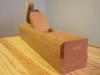
    This is a manual shaper. The lever that moves the shaper head back and forth consists of two flat bars and three bolts.

    If you're interested, here's a video that shows a similar shaper in action (it's a gas!):


    I need to know two things. First, what do you call this type of lever/crank/linkage/whatever? And second (and more important), how can I calculate the appropriate lengths for the two flat bars, for a given length of travel (for example, suppose I want 6 inches of travel)?

    In case anyone thinks I'm crazy: no, I'm not building a shaper. But I want to build a much simpler device that would use the same type of lever.

    I've found lots of things online that are similar, like Bell cranks, but I can't find this exact type of lever, and I've completely struck out on an explanation for the math. I suppose I could just do trial and error, but I'd like to know the theory.

    Any help is much appreciated; thanks in advance.
    Last edited by Steve Voigt; 04-10-2016 at 6:04 PM.
    "For me, chairs and chairmaking are a means to an end. My real goal is to spend my days in a quiet, dustless shop doing hand work on an object that is beautiful, useful and fun to make." --Peter Galbert

  2. #2
    Join Date
    Jul 2007
    Location
    NE OH
    Posts
    2,626
    Pretty cool gadget!

    First, I'm an EE not an ME but I play at being an ME.

    And...I don't know what it's called.

    However...I made a sketch showing the starting, middle, and ending position because those are the boundary cases.

    Lets call the pivot on the end of the long arm the end pivot, and the pivot in the middle of the long arm the middle pivot, and the pivot at the end of the short bar the stationary pivot.

    If you make the distance between the end pivot and the middle pivot equal to the desired stroke, and make the distance between the end pivot and the stationary pivot equal to 1/2 the stroke, it will work. There's no magic to it, you can alter them a little and it will still work because it's not that fussy.

    The spacing between the stationary pivot and the centerline of the sliding carriage should be .933 times the stroke length. This will center the motion of the end pivot and give the most balanced mechanical advantage.

    The ratio of the total length of the long bar to the distance between the middle pivot and the end pivot determines the mechanical advantage and hence, how much force you can apply to the tool.


    So, for 6" stroke, make the distance from the end pivot and the middle pivot 6 inches. Make the distance between the end pivot and the stationary pivot 3 inches. Locate the stationary pivot 5.6 inches away from the centerline of the moving carriage. Make the business end of the long arm as long as needed to get the force needed at the tool.

    I know this cries out for drawing; I can do one later when I have more time. Have fun!

  3. #3
    Join Date
    Jul 2007
    Location
    NE OH
    Posts
    2,626
    Wanted to add something: If all that is needed is linear motion driven by a lever, the end pivot can be fixed, and the middle pivot replaced by a pin that slides in a slot in the long arm.
    The purpose of the second link is to provide a way to drive the "self-act" mechanism that moves the carriage sideways by means of a ratchet. So what I called the stationary pivot actually turns back and forth with each cycle and that motion is used with a ratchet to drive the lead screw that moves the carriage sideways.

  4. #4
    Quote Originally Posted by Paul F Franklin View Post
    Pretty cool gadget!

    Lets call the pivot on the end of the long arm the end pivot, and the pivot in the middle of the long arm the middle pivot, and the pivot at the end of the short bar the stationary pivot.

    If you make the distance between the end pivot and the middle pivot equal to the desired stroke, and make the distance between the end pivot and the stationary pivot equal to 1/2 the stroke, it will work. There's no magic to it, you can alter them a little and it will still work because it's not that fussy.

    The spacing between the stationary pivot and the centerline of the sliding carriage should be .933 times the stroke length. This will center the motion of the end pivot and give the most balanced mechanical advantage.

    Paul, thank you so much for all the fantastic information! This is actually more than I hoped for.
    If you feel like elaborating…what's the reason for the 0.933 multiplier? I trig'd it out, thinking that the angles might be important, but they didn't seem to be…maybe I'm missing something…anyway, thanks again!!
    "For me, chairs and chairmaking are a means to an end. My real goal is to spend my days in a quiet, dustless shop doing hand work on an object that is beautiful, useful and fun to make." --Peter Galbert

  5. #5
    Quote Originally Posted by Paul F Franklin View Post
    Wanted to add something: If all that is needed is linear motion driven by a lever, the end pivot can be fixed, and the middle pivot replaced by a pin that slides in a slot in the long arm.
    The purpose of the second link is to provide a way to drive the "self-act" mechanism that moves the carriage sideways by means of a ratchet. So what I called the stationary pivot actually turns back and forth with each cycle and that motion is used with a ratchet to drive the lead screw that moves the carriage sideways.

    I was originally thinking of a slotted arm, but with no mill, putting a slot in a piece of steel bar stock is definitely an issue. What I liked about the design above is that it's doable with a hacksaw and a drill press.

    Still, it's good to know what the real purpose of the "stationary pivot"is. Maybe I could do something with that…Hmm…
    "For me, chairs and chairmaking are a means to an end. My real goal is to spend my days in a quiet, dustless shop doing hand work on an object that is beautiful, useful and fun to make." --Peter Galbert

  6. #6
    Join Date
    Jul 2007
    Location
    NE OH
    Posts
    2,626
    Well, assuming I figured it correctly...

    When the stroke is in the middle, the end pivot is as far away from the carriage centerline as it ever gets. When the stroke is at either end, the end pivot is as close to the centerline as it ever gets.

    I think the difference is (S is stroke length) S- (1/2*S/Tan 30) or S(1-(.5/Tan30)) or .134S. So the farthest is S and the closest is S- .134S. I wanted the "stationary" pivot to be 1/2 of that difference so it is in the center of the motion, so S-(.134S/2)= .933S

  7. #7
    Quote Originally Posted by Paul F Franklin View Post
    Well, assuming I figured it correctly...

    When the stroke is in the middle, the end pivot is as far away from the carriage centerline as it ever gets. When the stroke is at either end, the end pivot is as close to the centerline as it ever gets.

    I think the difference is (S is stroke length) S- (1/2*S/Tan 30) or S(1-(.5/Tan30)) or .134S. So the farthest is S and the closest is S- .134S. I wanted the "stationary" pivot to be 1/2 of that difference so it is in the center of the motion, so S-(.134S/2)= .933S
    That makes sense. Thanks!

  8. #8
    Join Date
    Jan 2009
    Location
    Williamsburg,Va.
    Posts
    12,402
    Those little manual shapers were popular in England many years ago. Made for home shop use. You could actually buy casting kits to make one for yourself and save yourself a pound or two. I have never seen one in person. I'll bet it can get pretty exhausting actually using one of those to make a project!

    The person who had one of those also probably had a metal working treadle lathe to go with it. And,maybe a hand cranked small drill press the size of an egg beater drill screwed to his bench. He would have been the envy of the neighborhood! But,with such rudimentary equipment,many a fine small steam engine or similar model engineering project was made.
    Last edited by george wilson; 04-11-2016 at 10:01 AM.

  9. #9
    Join Date
    Dec 2015
    Location
    Dublin, CA
    Posts
    4,119
    Quote Originally Posted by Steve Voigt View Post
    That makes sense. Thanks!
    I held off on posting here because this is a fairly tricky problem. I'm not convinced that Paul's analysis is complete, but I would be shocked if it's off by more than 10% - if that's good enough for you then we can leave it there. If not then I can simulate a range of geometries for you to get fairly exact answers.

    I have one question: Does your shaper travel as far in both directions as the short bars on the left will allow?

    EDIT: You may also want to look at leverage (specifically uniformity/profile thereof) when selecting the link sizes in one of these things. Rotation of the short link changes the velocity of the carriage (compared to a simple lever with a fixed end) by a varying amount, and that means the mechanical advantage is nonuniform (I think).
    Last edited by Patrick Chase; 04-11-2016 at 7:37 PM.

  10. #10
    Quote Originally Posted by Patrick Chase View Post
    I held off on posting here because this is a fairly tricky problem. I'm not convinced that Paul's analysis is complete, but I would be shocked if it's off by more than 10% - if that's good enough for you then we can leave it there. If not then I can simulate a range of geometries for you to get fairly exact answers.
    Patrick,
    I'm sure 10% is plenty good enough. Still, I know this is your area, so if there's anything you want to add in terms of the geometry, I'd certainly be interested.

    Also, I'd still love to know what the thing is called, and if you can point me to any online (or offline) reading that would help me get a bigger-picture understanding, that would be most helpful. I don't mind if it's mathy, as long as it's clear.

    I have one question: Does your shaper travel as far in both directions as the short bars on the left will allow?
    I don't have that tool (I wish!), it's just a picture from lathes.co.uk. (a great site, btw). So, I don't know.
    "For me, chairs and chairmaking are a means to an end. My real goal is to spend my days in a quiet, dustless shop doing hand work on an object that is beautiful, useful and fun to make." --Peter Galbert

  11. #11
    Steve,

    My terminology I would call this a linkage and slider mechanism, quick search seems its also called a slider-crank mechanism. My rough robotics backgrounds, I can vaguely remember since it's been a few years, but typically I have used Denavit–Hartenberg parameters to solve problems similar to this which is more complex than you are looking for I think.

    I think this walks through the math fairly well, the link a2 in the diagram in the web link below, doesn't extend past the joint as the mechanism you are looking at does, but has the appropriate motion and constraints are applied.

    http://ocw.metu.edu.tr/pluginfile.ph.../6/ch7/7-2.htm

    Bob
    Last edited by Robert McNaull; 04-12-2016 at 12:21 AM. Reason: terrible grammer

  12. #12
    Hi Robert, thanks for the link and the info, I'll dig into this.
    "For me, chairs and chairmaking are a means to an end. My real goal is to spend my days in a quiet, dustless shop doing hand work on an object that is beautiful, useful and fun to make." --Peter Galbert

  13. #13
    Quote Originally Posted by george wilson View Post
    Those little manual shapers were popular in England many years ago. Made for home shop use. You could actually buy casting kits to make one for yourself and save yourself a pound or two. I have never seen one in person. I'll bet it can get pretty exhausting actually using one of those to make a project!

    The person who had one of those also probably had a metal working treadle lathe to go with it. And,maybe a hand cranked small drill press the size of an egg beater drill screwed to his bench. He would have been the envy of the neighborhood! But,with such rudimentary equipment,many a fine small steam engine or similar model engineering project was made.
    George,
    A lot of those machines are very sturdy and well-made, though small in scale. I would love to have some of them! They tend to fetch high prices these days.
    "For me, chairs and chairmaking are a means to an end. My real goal is to spend my days in a quiet, dustless shop doing hand work on an object that is beautiful, useful and fun to make." --Peter Galbert

Posting Permissions

  • You may not post new threads
  • You may not post replies
  • You may not post attachments
  • You may not edit your posts
  •