Hi David,
I don't want to bust your bubble, but indicators rarely travel exactly 1" when they say 1". You have all sorts of errors that can show up, if you don't have the plunger perfectly parallel in two axis to the direction of movement you get a sine error. If your indicator actually swings .0997" per .1000" revolution, by the time you spin it 10 times for an inch, you can be quite a bit off.
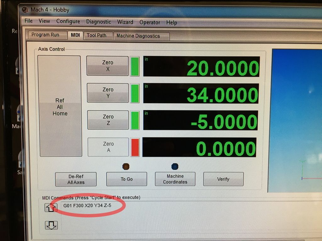
You should set travel distances using an accurate gage block, for example your Z axis, put the indicator into or on the spindle, set a 123 block on the table in the thin direction, 1" thick. Stand another 123 block on top of it so it is 3" tall. Zero your indicator in the top of the 3" block, slide it out of the way and using MDI command a Z-3.0 move and see if you get zero on the indicator again. You can do the same thing in the X and Y axis, just have to clamp one block solid so it doesn't move. I like to use 123 blocks as they are usually accurate on size within probably less than .0002", but I also have gage blocks called "jo blocks" up to 6" long in a single piece and like to use those too.
Brian Lamb
Lamb Tool Works, Custom tools for woodworkers
Equipment: Felder KF700 and AD741, Milltronics CNC Mill, Universal Laser X-600


Originally Posted by Paul Lawrence


 Reply With Quote

 Please help support the Creek.