Some parts to consider
Coolant for the spindle
Leak proof disconnects for your coolant hose
Flow indicator inline with coolant hose
Wiring for the fans on your radiator/pumpvassembly
Kentcnc dudt shoe
Few er20 collets


 Member
Some parts to consider
Coolant for the spindle
Leak proof disconnects for your coolant hose
Flow indicator inline with coolant hose
Wiring for the fans on your radiator/pumpvassembly
Kentcnc dudt shoe
Few er20 collets
Glad its my shop I am responsible for - I only have to make me happy.
 [OP]
Contributor
[OP]
Contributor
Thanks for the tips, Mike! I just checked tracking on the spindle mount and while I thought it would be here today it looks like tomorrow is the day. Moving forward!Originally Posted by Mike Heidrick

David
CurlyWoodShop on Etsy, David Falkner on YouTube, difalkner on Instagram
[OP]
Contributor
Quick question - I see VFD's mounted inside panels/enclosures and others mounted away from the machine on a wall or column; which is better? Do they need to be on a wall or column away from the machine for heat and vibration reasons, quick access to the control panel, etc., or is it just personal preference?
David
CurlyWoodShop on Etsy, David Falkner on YouTube, difalkner on Instagram
 Member
David...
If you can adhere to the clearance specs from the VFD and assuming the control cabinet has ample cooling, my preference is to mount them inside the control box. That said, problems can be created by EMF with some lesser cost components and possibly controls that seem to be more susceptible than others.
Gary Campbell
CNC Replacement & Upgrade Controllers
Custom 9012 Centroid ATC
Member
Lots of factors to consider:
What are the temperature operating limits for your VFD?
What is the expected ambient high temperature at the panel location in shop? (while VFD is operating)
How many heat producing devices in the panel? (VFDs, xfrmrs, power supplies, etc.)
Does the panel have any cooling provision? (A/C, powered vents, convection vents)
How big is the panel? (larger surface area can dissipate more heat)
If VFD is mounted external to panel, will it's heat sinks/fan get coated in dust?
Visit Hoffman Enclosures website (no affiliation) and they have loading/sizing calculator that can help.
Or for easy option, once in steady-state operation, you can place a thermometer in the panel (near top) and check to see if you are near the temperature limit for devices in the panel. If at or above any limits, move a device out (either the biggest heat generator, or the one with lowest heat tolerance). Or, look at panel coolers - - see Hoffman or Rittal.
Edit: I just remembered working with an enclosure where the manufacturer had un-bolted the heat sink (fins) from several devices, then drilled thru the enclosure's back wall in matching pattern. They then placed the heat sinks outside the enclosure, but still bolted up snug to the respective parent device inside. (The back panel in the enclosure was not installed in this area.) Conduction being more efficient than convection, most of the heat went thru the enclosure wall and into the heat sinks - outside the enclosure. ...Something to keep in mind?
Last edited by Malcolm McLeod; 07-27-2016 at 12:03 PM. Reason: external heat sinks
[OP]
Contributor
Thanks, Gary! I'm using the ESS, Keling digital stepper drivers, and shielded cable to the steppers. The enclosure will have at least one cooling fan, maybe two. I understand EMF isn't as big an issue with the ESS.
David
CurlyWoodShop on Etsy, David Falkner on YouTube, difalkner on Instagram
[OP]
Contributor
Thanks for the reply, Malcolm!
Our shop is climate controlled, so when it's in the high 90's or low 100's outside with 80% humidity the shop is in the mid to high 70's at 40% humidity. Same for the winter - 20's or 30's outside and mid 60's inside at about the same humidity.
The panel will have one 5v and two 48v power supplies. Unless the stepper drivers and ESS create heat, of which I doubt, then that should be all.
I'll use at least one, maybe two cooling fans. Given that the air is in the 70's in the shop one will probably suffice.
There is some dust but I have an air circulator with filter plus DC system to use on the CNC and other tools. The dust is minimal except on the rare occasion I need to use the table saw more than a couple of minutes.
In my plastics injection molding years I used Hoffman all the time - good enclosures. But I'm trying to stick to a budget so I'm thinking of using an old desktop tower computer case for my enclosure. My plan is to take that apart today and see if it's large enough for everything. It also has a cooling fan and vents built in so that just might do the trick. I can shield it from dust pretty easily.
I have an infrared thermometer so it will be easy to open the panel and shoot the components to track heat. But it just might be easier to mount the VFD externally.
David
CurlyWoodShop on Etsy, David Falkner on YouTube, difalkner on Instagram
[OP]
Contributor
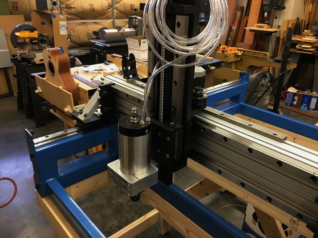
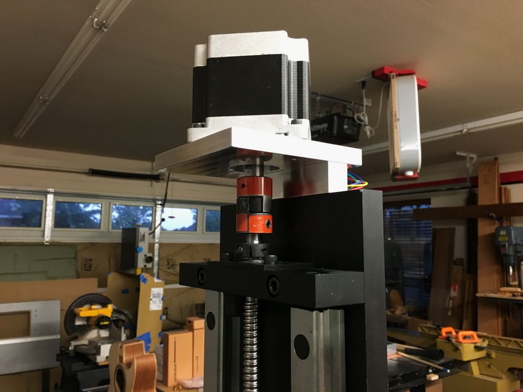
The spindle mount just arrived. I'm now 5 minutes closer to finishing - LOL! That's all it took to mount this, so while I can't run without it I figure I've only gained 5 minutes.
David
CurlyWoodShop on Etsy, David Falkner on YouTube, difalkner on Instagram
Member
That mount looks really nice, is it part of the frame kit?
[OP]
Contributor
Thanks, Ed, it does look nice - I agree! It was extra but it is definitely stout. I think Nate does it as extra in the event you already have one or want a different one. This one is 100mm to accommodate the 3kW spindle.
David
CurlyWoodShop on Etsy, David Falkner on YouTube, difalkner on Instagram
[OP]
Contributor
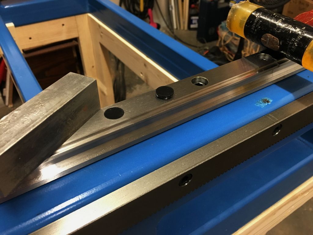
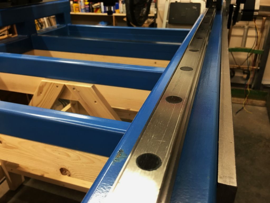
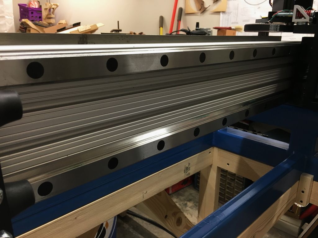
The screw caps also came in with the spindle mount and I had time tonight after church to put those on - 72 of them! That took a lot longer than mounting the spindle, for sure. But it will keep dust out of the screw holes and help lengthen the life of the bearings. After I put them in I dressed each one down to make sure nothing was sticking up proud of the surface.
David
CurlyWoodShop on Etsy, David Falkner on YouTube, difalkner on Instagram
[OP]
Contributor
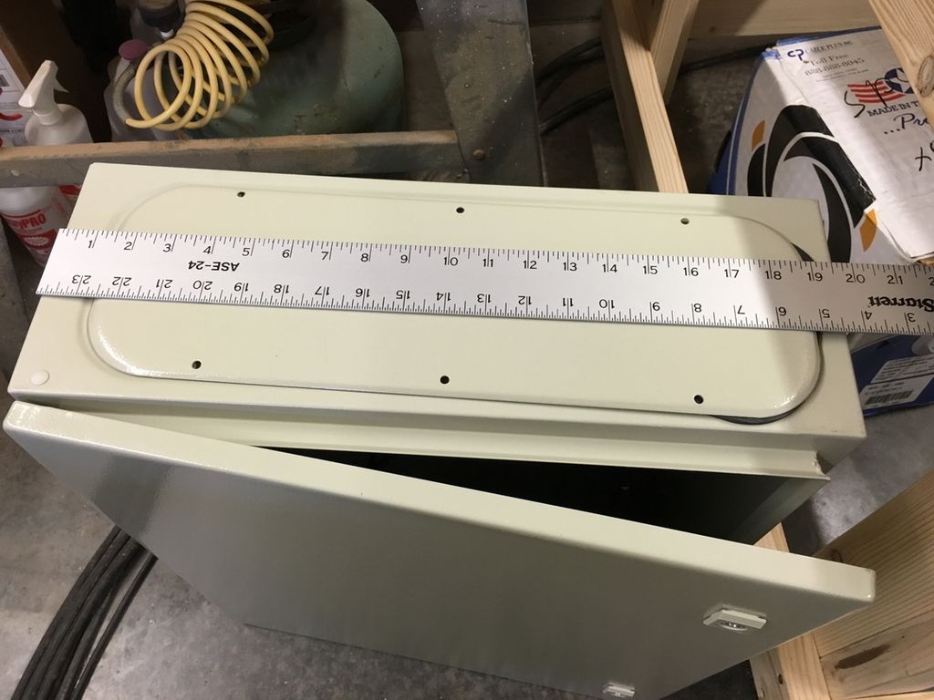
Well, bummer... I am all set to wire the enclosure this weekend and my box arrived on time from Amazon, as usual. However, for the first time in a long time they sent the wrong item. I ordered a 16x16x8 enclosure and they sent a 20x24x8 box. That would be ok if it would fit but it is way too large and I'm gonna have to send it back. I'd have to modify the stand or mount it somewhere off the machine for this to work for me and I don't wish to do either of those.
David
CurlyWoodShop on Etsy, David Falkner on YouTube, difalkner on Instagram
[OP]
Contributor
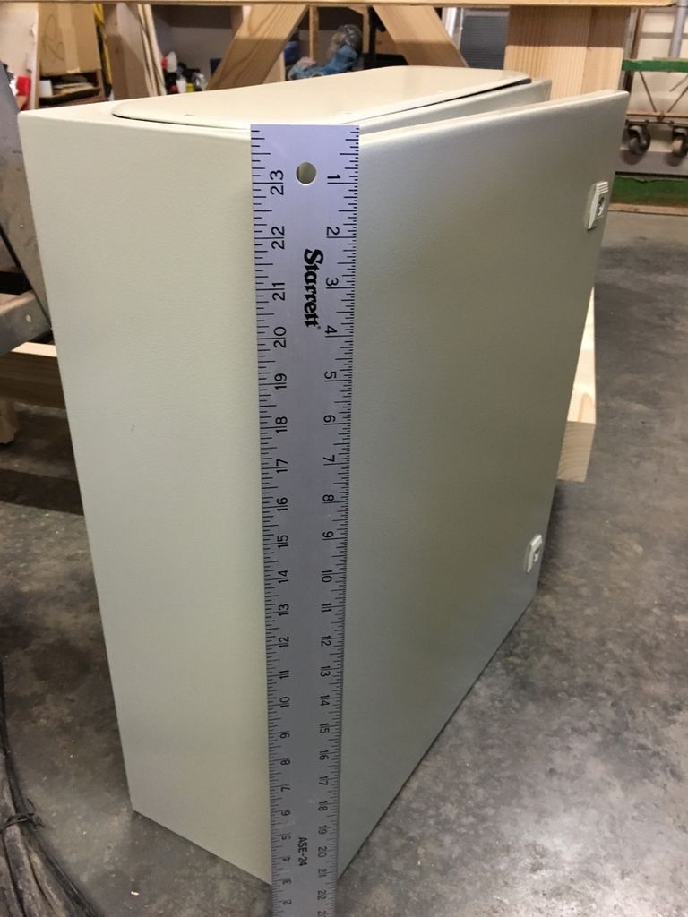
Well, the 16x16x8 enclosure came in today from Amazon and it appears God was watching out for me via Amazon shipping the 24x20x8 enclosure on Friday. I typically plan to the last little detail but on the enclosure choice I never laid out all the components, just assumed 16x16x8 would be sufficient. Man, was I wrong!! So I'm keeping the larger (wrong) one sent on Friday and shipping back the smaller one.
I loosely laid out the components on the back plate and there's no way this would have ever fit on the smaller one -
David
CurlyWoodShop on Etsy, David Falkner on YouTube, difalkner on Instagram
[OP]
Contributor
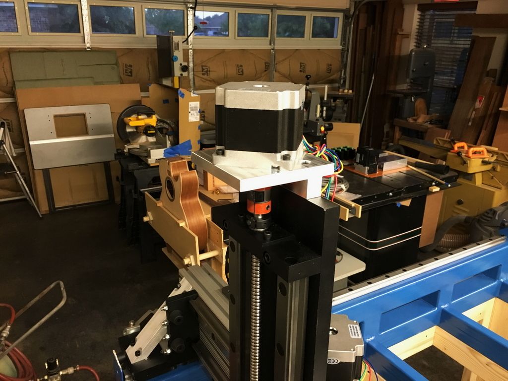
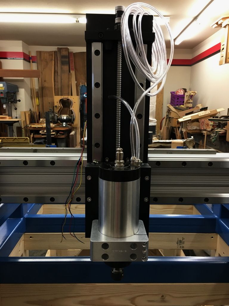
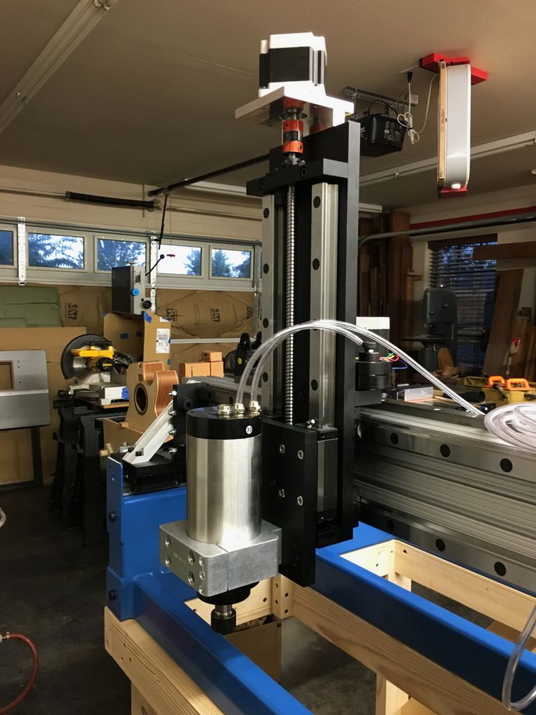
The spacer for the Z axis motor came in today along with the correct 14mm flex mount so now that's complete (except wiring) -
This measurement doesn't mean anything but for scale it is 31" from the top of the motor to the bottom of the spindle nut -
David
CurlyWoodShop on Etsy, David Falkner on YouTube, difalkner on Instagram
[OP]
Contributor
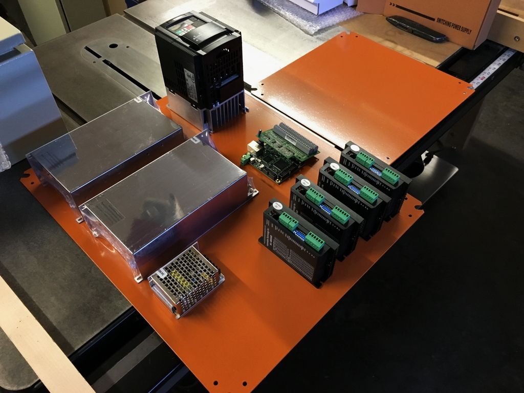
More of the electronic components came in today but I am waiting on a 12V power supply (just ordered today due to a change in plans from the way I originally intended one component), a terminal strip, and a few connectors. I'll likely make a little platform for the 5V and place the 12V PSU under it to save some back plate space. I'll be sure to give it enough space for all to remain cool but there's no reason not to stack these.
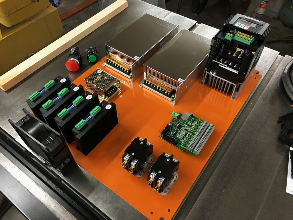
The pushbutton switches are both momentary with the green start button being NO and the red mushroom button being NC. The circuit I have designed will close the relays and start the power supplies and fans with the green button but nothing else will run until directed by the controller software. If I install a manual jog then that would work, though. The red button is not an emergency stop though it would have the same effect. It will cause the relays to open and there would be no power at all to the components. These pushbuttons will be at the opposite end of what I would call the 'front' of the machine so even though the red button is accessible I'll have other real e-stop switches located in better places for immediate use.
The relays in the bottom right corner will be for 120VAC and 240VAC. Only one of the contactors will be used on the 120V unless I decide to split the load and use both. The 240V relay will only be used for the VFD/Spindle. Both will open in the event of a power loss and that ensures the system won't restart on its own when power is restored.
I'm also allowing enough room for one more stepper driver for a future A axis installation. I'll go ahead and drill/tap the holes for it but will get the driver later. There will be a second and smaller fan to the right of the VFD and it will blow out. The bottom fan will blow in across the stepper drivers and power supplies.
So this is what it looks like in my initial layout, which is of course subject to change -
David
CurlyWoodShop on Etsy, David Falkner on YouTube, difalkner on Instagram
 Posting Permissions

 Reply With Quote