Page 1 of 3 123 LastLast
Results 1 to 15 of 42

Thread: Dust Extraction Duct Routing - High or Low?

  1. #1
    Join Date
    May 2017
    Location
    Germany
    Posts
    610

    Dust Extraction Duct Routing - High or Low?

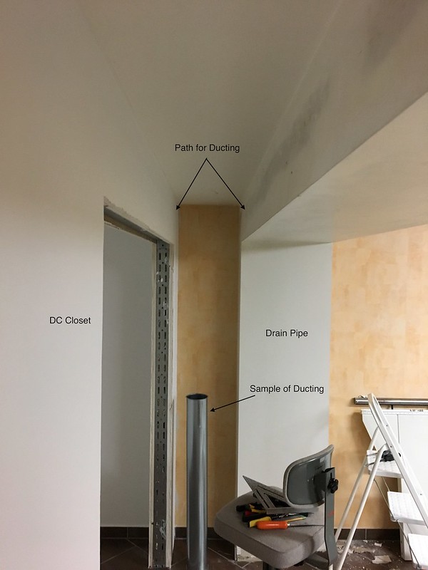
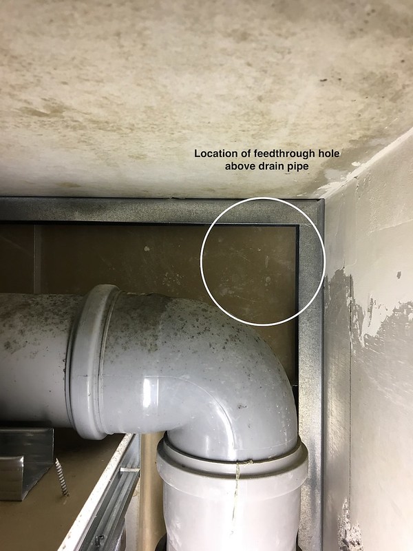
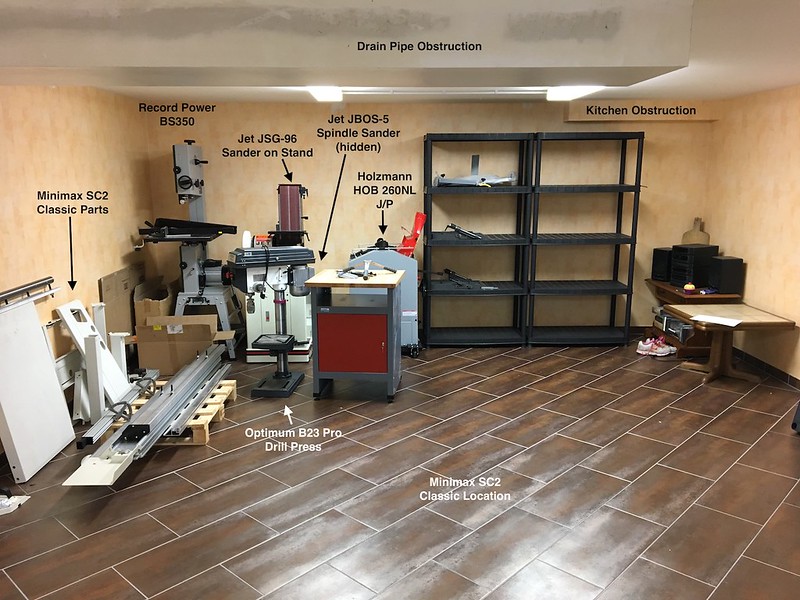
    I am in the process of building my basement workshop and have a blank slate for the dust collection system. The dividing wall that separates the shop from the rest of the semi-finished basement is in, but the standard metal door will not be delivered and installed until the middle of August (it's a German thing). The main shop is 5m x 4.75m (16.4 x 15.6 feet) and has a separate closet that is 1m x 2m (3.3 x 6.6 feet), for the dust collection and air compressor. The double doors for the closet have to be cut down to clear the drain pipe obstruction that runs across the ceiling, and will be delivered and installed sometime in late September (yes, more of that German thing). I have plenty of free space to work in and want to install the dust collection ducting and power distribution now. The installation of the cabinets, shelving, and benches, as well as final placement of the equipment will be done later.

    I have a 2HP dust collector that I will reconfigure and combine with an Oneida Super Dust Deputy (the metal version) and a pair of Wynn filters. However, I have still not made up my mind about the location of the 120mm metal ducting that will go around three walls of the shop. All of the shop installations I see have the main ducting mounted high, with either rigid down tubes along the wall ending at blast gates near the floor, or blast gates mounted high, with flexible tubing going down the wall to the equipment. Is this done because in most cases the dust collection system was added after the shop was built?

    Is there a reason the main ducting could not be mounted low on the wall, with the only rise up the wall at the dust collection equipment? In the two basic scenarios I drew, the horizontal and vertical travel for chips and dust were the same for each piece of equipment. The difference was the cost of material for the ducting, with the high version being more expensive. Does the location of the point where the chips and dust rise make a difference? In my simple way of thinking, the particulate has an opportunity to increase velocity if it is not trying to overcome gravity at the start of the journey to the cyclone.

    Given the opportunity to start over, would anyone reconsider the location and routing of the dust collection ducting? I welcome all comments and suggestions, as I don't want to make major changes to the system after it's installed.

    To avoid starting another thread, I would appreciate opinions on the air compressor. I don't know what would be a reasonable size for small nail and brad guns. I don't intend on painting or sand blasting in the shop, but want the opportunity to use a few air tools. I have plenty of room in the closet for a compressor, and will have a 16A 400V 3-phase receptacle for it and the dust collector. What is a reasonable size for the compressor and air tank?

  2. #2
    Join Date
    May 2005
    Location
    Highland MI
    Posts
    4,521
    Blog Entries
    11
    Low on the wall can be in the kick space when standing or moving. High on the wall is out of the way and material travelling up may be in a smaller duct or hose than your final run up if your main run is low. Example, 4" duct to a smaller machine with lower flow will now have to travel up at the end of the main run in, say, a 6" duct where the velocity may not be enough to carry large chips and small off-cuts. That being said, here is my run from the MS and TS, but I am keeping the MS duct at 6" and the TS hose at 5". Only once have I had to remove off-cuts from the upward turned bend.
    Attached Images Attached Images
    NOW you tell me...

  3. #3
    Join Date
    Mar 2003
    Location
    SE PA - Central Bucks County
    Posts
    65,848
    There's no major dust collection efficiency advantage/disadvantage to either level as long as duct length and bends, etc., are similar. As Ole mentions, there may be practical shop-space/utilization/workflow factors that will make one better than the other.
    --

    The most expensive tool is the one you buy "cheaply" and often...

  4. #4
    Join Date
    Feb 2008
    Location
    E TN, near Knoxville
    Posts
    12,298
    Mike,

    I designed my shop from the ground up and chose to put my ducts high, in fact, I put them in the trusses above the ceiling and brought down 6" pipe to the machines. I did this to get them out of the way. The wall and floor space in my shop is precious and mounting them high got them out of the way and gave me far more flexibility for positioning things. Also, I ran one main line down the middle and branched out to various tools, not possible if mounted low. The system works very well (5hp ClearVue).

    DC_duct_IMG_20141228_195036.jpg

    It was a real challenge to snake the ductwork through the trusses without notching a single truss. It would have been a LOT easier to just run them up against the ceiling but that would limit some other things like light placement and high shelves. I ran the HVAC ducts up there too. I'm quite pleased with how it turned out.

    As for the air compressor, I opted for a 60 gal 5HP 2-stage compressor. I use nail guns but also air up tractor tires, use impact wrenches, and pneumatic random orbital sanders. The compressor doesn't run as much as it would with a smaller tank. This is more air then you would need for a few air tools but it gives the capacity to do more in the future if things change. The way I look at things like this, the cost of the equipment for more capacity is tiny compared to the total cost of the shop! Adding it now would be a lot simpler and cheaper than upgrading it later.

    One thing I did for the air compressor was to run the air through the wall into the main shop so I don't have to go into the closet except to drain the tank. On the wall in the main shop I have an electrical disconnect, gauges, dryers, regulator, and valves. The air lines are plumbed in the walls and ceilings and go to 8 outlets around and outside the shop. I used the 1/2" RapidAir piping and outlet kits.

    air_comp_ctrls_IMG_20150124.jpg

    JKJ

  5. #5
    Join Date
    Sep 2016
    Location
    Modesto, CA, USA
    Posts
    9,975
    If your compressor is hidden in a closet add an automatic drain valve that blows through a hose through the wall to the outside.
    Bll

  6. #6
    Join Date
    Mar 2006
    Location
    SoCal
    Posts
    22,510
    Blog Entries
    1
    In my shop, wall space (both low and high) is precious. High ducting takes up space in the areas least likely to be used for other things. I have ducts high and low and both work fine. If your ceiling is low there is always the temptation to use tight 90 degree bends at the ceiling/wall or wall/wall junctions. Try to avoid this by using long sweeps or dual 45 degree fittings with a section of straight pipe between. These protrude into the work space more but, a nice looking inefficient duct system is no fun.
    "A hen is only an egg's way of making another egg".


    – Samuel Butler

  7. #7
    Join Date
    Mar 2003
    Location
    SE PA - Central Bucks County
    Posts
    65,848
    John makes mention of something that's very important...routing for efficiency. You ultimately want the minimum duct length and elbows for best performance and running anything around the perimeter is often the direct opposite of that. Hence, the propensity of duct work to be "up high" (or under the floor) so that more direct routing can be facilitated. That's often on a diagonal across the shop for a main trunk, too, depending on where the DC lives permanently in relationship to the tools it will be servicing.
    --

    The most expensive tool is the one you buy "cheaply" and often...

  8. #8
    Join Date
    Mar 2015
    Location
    Birmingham, MI
    Posts
    148
    Mike,

    I would say efficiency and cost should be cheaper going on the ceiling. I say this on the basis of a main line going straight across the ceiling and wyes breaking off to the equipment as compared to your plan of going around the walls to your equipment. If your DC is in a corner then this main line would go on a diagonal (otherwise down the middle). You don't have a large shop and you are doing the right things with a SDD and larger filter area to keep efficiency up, but you are on the borderline of available CFM using a 2HP DC. Does your DC have a 12" or larger impeller? (that will assure you are starting with enough CFM at your DC). I know going around the room is more tidy but you are adding more 90s and distance between your machines and your DC (which lowers your DC efficiency) Each 90 adds about 9 feet of straight pipe to your already long run of 15 feet per wall times 3 walls plus 2-3 90s is well over 60 feet of pipe just to get to the machine then you add wye's gates, flex, etc.

    (check this guide http://www.woodweb.com/knowledge_bas...sign_guide.pdf)

    The other thing is to get the most efficient setup you will be stacking your blower on top of your SDD which should have your intake close to the ceiling anyways.

    On a separate question, does your blower spin the intake air in the same direction as the SDD will spin the intake - when mounted on the SDD? (If not a simple air straightener will help with noise and efficiency).

    Hope this helps. Let us know what you do.

    Carl

  9. #9
    Join Date
    May 2017
    Location
    Germany
    Posts
    610
    Thanks to everyone for the replies and helpful comments. I decided on a ceiling mounted ducting system after confirming the 120mm pipe will just fit through the corner formed by the ceiling, wall, and sewage pipe that runs across the shop ceiling. I tried a section of DIN110 PVC drain pipe, but the outer diameter is too large to fit in the gap.

    I wish I had the ability to run the pipes in joists or run diagonal across the room, but the house was constructed with cast in place reinforced concrete walls and horizontal slabs. My hammer drill gets a workout knocking holes in the walls and floors. Aside from the doors, the only non-concrete structure forming the shop is the GWB wall I had installed last week. The main sewage drain for the house is hidden in a GWB box that allows for the PVC pipe slope as it leaves the building. In one corner of the room, there is another boxed area for the kitchen domestic water and drain. I used two 45-degree elbows to jog around the kitchen obstruction, but I can eliminate them if I don't keep the DC duct flush against that wall.

    Here is a rough drawing showing the proposed duct routing. I placed the jointer/planer near the door in case I have to run long pieces through it. All ducting is 120mm, and the blast gates are on the 45-degree splitters. I will use 120mm flexible tubing to go down the wall to the machines. The Minimax saw also has a smaller flexible duct connected to the overhead 120mm metal duct, through a reducer, above the blade guard.

    The ceiling obstructions are shown in very light dashed lines. The largest is the main sewage line that enters the basement near the main door and exits the house at the top of the drawing. The other obstruction for the kitchen is in the lower right corner.

    Shop-1-Model.jpg

    Please feel free to critique the layout, but also understand I am limited to the space available.

    Here is a link to the Holzkraft page for the DC ducting I will be using.
    Last edited by Mike Kreinhop; 07-21-2017 at 6:03 PM. Reason: Added a comment.

  10. #10
    Join Date
    May 2017
    Location
    Germany
    Posts
    610
    Quote Originally Posted by Carl Kona View Post
    The other thing is to get the most efficient setup you will be stacking your blower on top of your SDD which should have your intake close to the ceiling anyways.

    On a separate question, does your blower spin the intake air in the same direction as the SDD will spin the intake - when mounted on the SDD? (If not a simple air straightener will help with noise and efficiency).
    Thanks, Carl. I will be mounting the blower over the SDD, and it does spin in the same direction as the airflow in the SSD. I measured the impeller as soon as it arrived, but I can't remember the diameter, but remember it was over 12 inches in diameter.

  11. #11
    Join Date
    Mar 2003
    Location
    SE PA - Central Bucks County
    Posts
    65,848
    Good start on the design. Please consider extending the trunk from the saw down to the J/P and a small drop to the DP from there. The J/P is probably the most demanding tool in the shop relative to volume and that long perimeter run is going to kill performance.
    --

    The most expensive tool is the one you buy "cheaply" and often...

  12. #12
    Join Date
    Jan 2010
    Location
    Tampa Bay, FL
    Posts
    3,925
    Quote Originally Posted by Jim Becker View Post
    Good start on the design. Please consider extending the trunk from the saw down to the J/P and a small drop to the DP from there. The J/P is probably the most demanding tool in the shop relative to volume and that long perimeter run is going to kill performance.
    +1.

    No matter how I modified it, I can't get good dust collection from my Laguna J/P even with a 5HP Oneida, so I'd work hard on maximizing the flow from that.
    - After I ask a stranger if I can pet their dog and they say yes, I like to respond, "I'll keep that in mind" and walk off
    - It's above my pay grade. Mongo only pawn in game of life.

  13. #13
    Join Date
    Feb 2003
    Location
    Washington, NC
    Posts
    2,387
    Quote Originally Posted by Mike Kreinhop View Post
    Thanks, Carl. I will be mounting the blower over the SDD, and it does spin in the same direction as the airflow in the SSD. I measured the impeller as soon as it arrived, but I can't remember the diameter, but remember it was over 12 inches in diameter.
    Why is the ducting around the perimeter of the shop? That is the longest route and longest run requires 3 90° bends. As you know you should avoid 90's at all costs. A hypotenuse is much shorter than the sum of the sides. With only a two hp DC you need the most efficient layout possible (shortest runs, fewest bends). A 2 hp unit is not suited for a fixed, ducted setup. If you can, depending on the plumbing obstructions, consider these layouts - shorter individual runs and no 90° bends. It will require more duct, but the run from every tool to the DC will be shorter than your design.


    Attached Images Attached Images

  14. #14
    Join Date
    Jan 2017
    Location
    Marina del Rey, Ca
    Posts
    1,936
    I see 2 options:

    A main duct running diagonally from the DC to approximately the DP

    or

    A main duct running first to the main saw port, then turning down the centerline to the JP.

    Other branches run at 45* from that.
    "Anything seems possible when you don't know what you're doing."

  15. #15
    Join Date
    May 2017
    Location
    Germany
    Posts
    610
    Thanks again for the comments! I attached more images of the workshop. The hideous wallpaper will be painted white this weekend.

    I can't make any diagonal runs across the ceiling because of the obstructions and the surface mounted lighting fixtures. I currently have two large fluorescent dual-tube fixtures, but will be replacing them with four smaller fixtures that are better suited for a workshop. I will take Jim's advice and will extend the overhead run for the saw to the J/P.

    The first image shows the drain pipe obstruction and its relationship to the DC closet and rest of the shop. In my original drawing, the obstructions are shown with light gray dashed lines.


    The next image shows the interior of the drain pipe box and the only path available to feed the 120mm duct. The duct just fits between the drain pipe and the corner formed by the ceiling and the wall.


    The last image shows the rest of the shop, with the equipment (minus the SC2 saw) stacked in the corner. The kitchen plumbing obstruction is shown in the upper right corner. The black plastic shelves holding the HOB260NL parts are temporary and will not be used in the shop.


    I haven't installed the electrical distribution yet, but will wait until after the walls and ceiling are painted and dry. Not shown in this image is the 32A three-phase distribution panel on the right side near the main door. We are fortunate in Germany to have three-phase service in residential buildings. The bandsaw, drill press, and J/P are single-phase, but I have the motor, contactor, and replacement components from Holzmann to convert the J/P to three-phase.

Posting Permissions

  • You may not post new threads
  • You may not post replies
  • You may not post attachments
  • You may not edit your posts
  •