


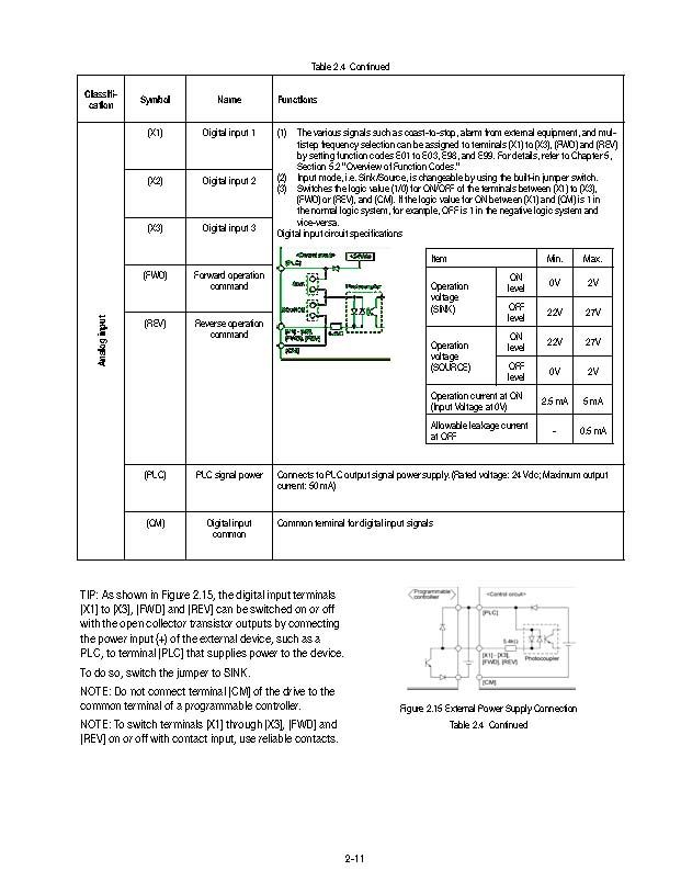
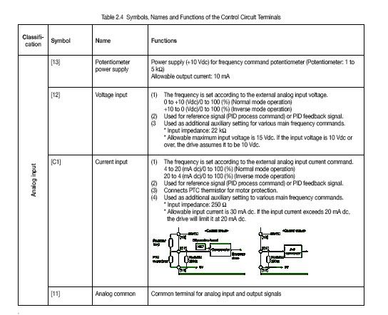
I am trying to setup my remote now and have some questions for all of you. I have included a list for the buttons/switches I am planning to buy to allow run, stop, forward & reverse, and speed control. Below are some pics from my vfd manual control terminals.
I am planning on purchasing the following parts from automationdirect.com
Pushbutton, 22mm metal, momentary, red 40mm mushroom operator, 1 N.C. contact block
Pushbutton, 22mm metal, momentary, black 40mm mushroom operator, 1 N.O. contact block
Selector switch, 22mm metal, 2-position, maintained, black knob, 1 N.O. contact block
22mm potentiometer with 10 Kohm resistance, black handle.
Four-hole plastic enclosure for 22mm devices, 185mm H x 70mm W x 51mm D, 40mm between hole centers, gray top
Number 13 on the contact terminal shows the power supply for the POT. The FWD and REV terminals, I assume, come from the output from the selector switch. I don't understand where to get the power for, or where the output goes for the other buttons/switches. Can anyone help me with the other connections.
Any help will be greatly appreciated.

 Reply With Quote


 Hmmm
Hmmm")

