Results 1 to 9 of 9

Thread: Yet another CNC observation/question

  1. #1

    Yet another CNC observation/question

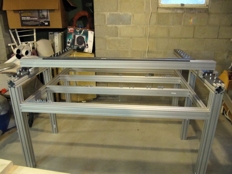
    Ok I have a working prototype of my new machine. When I say prototype I mean its mounted on a table the will be replaced with another once certain decisions are made.

    I built a version with the Y rail mounted directly on top of the two X carriages to form the gantry. In this design it is quite ridgid. More rdigid than any gantry design I have seen. The down side is that the stand is much more complicated as the table needs to be dropped below the Xrails. It also makes fixture/stock access much more difficult.


    The raised gantry (raising the Y rail about 12" above the X carriages makes for a more typical design and yealds easyer access to fixtures and stock. However it adds more mass and can slightly rack. While Im not concerned with the racking as I will be using dual X axis and this will aid in beign able to square up the table by adjusting the home swithces. The added steel mass may require that I upgrade to larger drivers and motors. Im not sure I am willing to do that.

    I have noticed that the larger cnc machines tend to use the former (Y rail sitting directly on X carriages).

    Any thoughs or comments are welcome.

  2. #2
    Join Date
    Nov 2007
    Location
    Glenelg, MD
    Posts
    12,256
    Blog Entries
    1
    Well, you've already seen the major trade-off. The higher you place the gantry above the rails, the higher the angular moment you have working at those joints... this means any change in the movement vector (direction/speed) will result in some "give" in actual position versus desired position (translation: temporary slop).
    Hi-Tec Designs, LLC -- Owner (and self-proclaimed LED guru )

    Trotec 80W Speedy 300 laser w/everything
    CAMaster Stinger CNC (25" x 36" x 5")
    USCutter 24" LaserPoint Vinyl Cutter
    Jet JWBS-18QT-3 18", 3HP bandsaw
    Robust Beauty 25"x52" wood lathe w/everything
    Jet BD-920W 9"x20" metal lathe
    Delta 18-900L 18" drill press

    Flame Polisher (ooooh, FIRE!)
    Freeware: InkScape, Paint.NET, DoubleCAD XT
    Paidware: Wacom Intuos4 (Large), CorelDRAW X5

  3. #3
    Join Date
    May 2009
    Location
    N.W. Missouri
    Posts
    1,564
    To me, low X rails looks like it would be easier to load and unload on larger machines. I went with a low rail design on my 36"x43" DIY router for that reason.

    John

  4. #4
    Join Date
    Oct 2006
    Location
    Bloomington, IL
    Posts
    6,009
    You guys have pictures of these designs?
    Glad its my shop I am responsible for - I only have to make me happy.

  5. #5
    Is this what you have in mind?

    Equipment: IS400, IS6000, VLS 6.60, LS100, HP4550, Ricoh GX e3300n, Hotronix STX20
    Software: Adobe Suite & Gravostyle 5
    Business: Trophy, Awards and Engraving

  6. #6
    Here is the high gantry version. If you look real close at the X carriage. The top bearing bar has 4 holes. These allow me to mount the 80/20 directly to the carriage.


    This higher gantry has another advantages as it make the overall design much easyer. Since its not too integrated with the table you can mount the rails on just about any surface as I have done here. By just loosening bolts I can adjust the width. In this design I have no side to side or front to back movement. The 2" angle Iron takes care of that. IT does however have a slight tendancy to rack. Im not sure but the two lead screws on each side should take care of this a little.

    Another disadvantage of the higher gantry is that any movement on the v berings is amplified by a facter related to the distance.

    I think I will be going with the lower gantry design but since its integrated into the table its harder to prototype.
    Last edited by Michael Simpson Virgina; 02-16-2011 at 4:16 PM.

  7. #7
    Join Date
    May 2009
    Location
    N.W. Missouri
    Posts
    1,564
    This is mine, during the wiring phase of construction.

    John
    Attached Images Attached Images

  8. #8
    Join Date
    Jan 2007
    Location
    State Capital, WI
    Posts
    470
    Michael -

    nice looking bearing setup and ease of carriage building, but I must warn you: the 2040 (2"x4") 8020 extrusions that you are using will exhibit a fair amount of twist due to lack of torsional rigidity of that extrusion when the machine is cutting in the X direction of you machine. The large moment arm that the extended Z carriage will place a load on that beam, and it will start to shake and shimmy during rapid moves and high acceleration direction changes. This has been observed on many machines on the Joe's forum and is well documents. The fix has been to install a full length 1/4" thick cold rolled steel plate on both sides of the gantry beam that extends through the gantry connection points.

    I know this from first hand experience.
    oops ....1,2,3,4,5,6,7,8,9,10 - yup all there, whew!

  9. #9
    I have to say I dont like the reply to thread button at the top of the Quick Reply post box. I cant tell you how many times I have hit that button after typeing a long response only to loose it all with a single button click. :{

    I had thought the 2040 10 series was a little more behaved than the metric 25 series since its a little thicker and a bit more mass.
    I only planned on using this prototype to get my Y carriage and z axis worked out and built then the gantry rail will be mounted directly ontop of the X carriages. I can attest that its much more ridgid than the raisd gantry shown here or the one used on the Joes build.

    That said more reenforcement can always be an upgrade option. Is the 1/4" bar 4" x 72" and mounted to the front and back of the gantry rail? How far appart did you mount your bolts. Did the added mass force you to use larger motors? Mine are 380 oz nema 23. Im driving 5 start screws so they will have more toque than the same motors driving a Rand P system.

    FYI I did do a lot of flex tests with 8020 2040 and did notice it had quite a bit of give at 72" length.

    This prototype allows me to test various spans of the gantry with only lostening bolts. I want to test at what point various size router loads start to chatter and vibrate. This will give me a good ref when I lower the gantry to the rails and add reenforcment.

    Oh.. The reason I am interested in beefing up the gantry with a 2" angle is that it would also give me a platform for my dragon cable (cable guide).
    Last edited by Michael Simpson Virgina; 02-18-2011 at 1:37 PM.

Posting Permissions

  • You may not post new threads
  • You may not post replies
  • You may not post attachments
  • You may not edit your posts
  •