Page 2 of 3 FirstFirst 123 LastLast
Results 16 to 30 of 36

Thread: Leg vise question

  1. #16
    Join Date
    Dec 2010
    Location
    Burlington, Vermont
    Posts
    2,443
    Somewhere I've seen it mentioned the idea of using a block hanging by a string to chock the bottom of the vise - slide it in place and it does the same job as the parallel guide. Give it a couple different dimensions and it works as two pin settings. Add another block hanging by a string for more combinations. You can still keep the holes in the parallel guide and a pin for when the jaws get opened wide. The same principle as using a spacer on the other side of a bench vise, just making the racking work for you, not against you.

    As Wilbur has said, with the pin in the right place, one setting probably works for most of your stuff.

  2. #17
    Join Date
    Jan 2009
    Location
    Williamsburg,Va.
    Posts
    12,402
    I'm sure there are ways to use a pedal,etc. to insert the pin. I haven't researched it since this issue hasn't been of concern to me. My el cheapo copy of a Record vise is working fine.

  3. #18
    Join Date
    Oct 2006
    Location
    East Brunswick, NJ
    Posts
    1,475
    Quote Originally Posted by george wilson View Post
    I do not see how there would be any loss of clamping power [with a St. Peter's cross]. It's just that the cross mechanism likely would not stand extreme tightening without flexing somewhere.

    Since the location of the vise screw limits the useful depth of the vise,I agree that raising the parallel guide is the more practical solution. Put a string on the pin to keep from dropping it if bending over is a problem(it's getting to be a problem for me!)
    The loss of clamping power comes from the fact that if the St. Peter's cross is doing its job and keeping the leg vice chop parallel to the face of the leg, then the clamping pressure will be spread over a larger area. With a pin and a parallel guide, you can set the pin so that the distance of the pin to the chop is slightly wider than the thickness of the board, so that the chop angles in slightly at the top of the leg vise in use, which concentrates the force over a smaller area, increasing the effectiveness of the clamping.

    It's just like a wooden screw clamp. If a wooden screw clamp is adjusted so that the faces of the clamp jaws angle towards each other slightly, you'll get more clamping pressure than if they are perfectly parallel.

    Raising the parallel guide will also decrease the clamping pressure, but this tends to be a more theoretic issue than a practical one.

    I do agree that given how much pressure you can get with a leg vise that a St. Peter's cross needs to be pretty beefy for it to hold up. The St. Peter's cross is essentially the fulcrum for the vise, and so it needs to be able to hold up to a lot of force. And if the St. Peter's cross doesn't keep the chop parallel to the leg face, you might as well just have a parallel guide and a pin.

  4. #19
    Join Date
    Nov 2006
    Location
    Trussville, AL
    Posts
    3,589
    Quote Originally Posted by Wilbur Pan View Post
    I do agree that given how much pressure you can get with a leg vise that a St. Peter's cross needs to be pretty beefy for it to hold up. The St. Peter's cross is essentially the fulcrum for the vise, and so it needs to be able to hold up to a lot of force. And if the St. Peter's cross doesn't keep the chop parallel to the leg face, you might as well just have a parallel guide and a pin.
    Any reason you couldn't have both, a parallel guide (with rollers) to help keep things even and smooth and the cross to take care of the racking?

  5. #20
    Join Date
    Mar 2012
    Location
    Mid coast Maine
    Posts
    480
    Let me throw my two cents in. I've had a leg vise in my shop for twenty-five years and would not be without one. Until recently they had the pin in the lower rail. The old screws had like a ball and socket connection at the handle joint.


    That type of fitting can handle something out of parallel. When I was asked to build 4 leg vises for our community boat shop we ordered new Lie-Nielsen bench screws. They are nicely made as you can imagine, they even have roller bearings in the handle joint. But they don't like being skewed. That led me to a bit of R&D and some searching and I now have a chain mechenisem on the left leg of the work bench I just built. It is adjusted to have the top of the jaw close moments before the rest of the leg. It requires no further attention from me. I was so pleased with it I contacted Jameel and he is considering it for his line of products. If he declines then I will be producing it. So it is not available at the moment, but it can be retrofitted to an existing vise.
    In the mean time there are two other ways that do not require the pin in the beam. Both involve a steel bar for the lower beam. Saw teeth are filed in the lower edge of the bar.
    Harry Bryan describes one in an article in Woodeboat magazine #179 July/August 2004. In his version the lower beam is ridged and you lift the whole jaw up the disengage the pawl that is mounted on the fixed leg.
    The other version I've seen is on page 124 of the Scott Landis Workbench book. The sketch depicts the notched bar pivoted on the movable leg and a pedal made from a bent piece of metal to lift the bar to disengage the pawl.
    I personally think the St Peters cross is kind of cool, but I think it would be difficult to install and there is no way to adjust for normal wear unless the legs are adjustable for length and that to me would be bulky and mor complicated to build. Just my thoughts on the subject.

  6. #21
    Join Date
    Jan 2009
    Location
    Williamsburg,Va.
    Posts
    12,402
    With all respect would not the presence of a pin in the usual way of adjusting the lower jaw of the vise also "spread out the clamping pressure"? The pin serves the same purpose as the cross design.

    I think this is another of those discussions that in the end are really moot: The vise will be sufficiently tightened in any case to do the work. Making the screw handle longer will make up for any mechanical loss,real or imagined.

    P.S.: Jim;The chain mechanism is a good way to build a vise,and I'd not be worried about it spreading out the pressure. Since you have used it already and like it,I'm sure it has served you quite satisfactorily.
    Last edited by george wilson; 03-28-2012 at 12:13 PM.

  7. #22
    Join Date
    Oct 2006
    Location
    East Brunswick, NJ
    Posts
    1,475
    Hi George,

    This is probably a situation where a picture is worth 1000 words.

    Here's a schematic diagram of a leg vise with a parallel guide and a pin set so that the distance from the pin to the chop is a little wider than the board being clamped, before and after clamping a board.

    As you tighten the leg vise, the pin runs into the bottom of the leg, and the top tilts in a little. The clamping force will be concentrated over a smaller area. On my vise, I have a piece of leather on the inside of the chop, which also helps. As I mentioned, you see the same thing with a wooden screw vise. Adjusting the screws so that the tips of the wooden screw vise are slightly closer than the back end concentrates the clamping power at the tips.

    Here's a leg vise with a St. Peter's cross, again before and after clamping a board.


    If the St. Peter's cross does its job, the face of the chop will stay parallel with the board, spreading the clamping force over a larger area.

    Clearly, you don't want too much of a tilt, because then you reduce the clamping area to a point where it does more harm than good. But I find that a little bit of a tilt is useful for clamping, which is why I can have the pin in just one position for clamping boards 1/2" to 1" in thickness.

    This is also why I think that a St. Peter's cross is going to be a lot more trouble than it's worth. As George said, you have to have pretty high tolerances for the mechanism to work correctly, and if you achieve that, there's no real difference in the ability of the leg vise to clamp a board. And if you don't get the St. Peter's cross to work perfectly, or if over time the forces cause it to bend so that the leg vise chop no longer is parallel to the face of the leg, then you've gone through all that trouble to make the St. Peter's cross to wind up with a mechanism that is the same as a parallel guide and a pin, which is far easier to make.

  8. #23
    Join Date
    Jan 2009
    Location
    Williamsburg,Va.
    Posts
    12,402
    At least we can agree that the cross is fraught with problems. As for the rest,I have managed to stumble through my woodworking career somehow.

  9. #24
    Join Date
    Oct 2006
    Location
    East Brunswick, NJ
    Posts
    1,475
    Exactly. The St. Peter's cross seems to be trying to solve a problem that doesn't really exist.

    And the issue of how much clamping force you can generate is a moot point as well. I brought it up mainly to show that the St. Peter's cross certainly wasn't going to improve the clamping ability of a leg vise, and might even reduce it.

  10. #25
    Join Date
    Mar 2012
    Location
    Mid coast Maine
    Posts
    480
    Thank Wilbur for the sketch up. Some day I need to learn that.

  11. #26
    Join Date
    Dec 2010
    Location
    Burlington, Vermont
    Posts
    2,443
    The biggest benefit of the racking motion of the pin is that it always holds the stock up at the top, near the bench. This is a good thing. If the St. Peter's cross ends up working less accurately in such a way that more of the clamping action is down at the bottom, it leaves less pressure at the top. This can lead to those very annoying vibrations when sawing parallel to the direction of the vise closing, particularly with thinner stock, even when you lower the work as low as you can and still do the work. This is the same reason many vises have a very slight cant to the jaws.

    It actually seems likely that this would be the way a cross would fail - as the mechanism is going to close on the work piece, which is probably less likely to compress or flex than the cross mechanism and everything it's attached to, the workpiece effectively becomes the pivot point the pin would be - and if you try and crank the vise tighter, things may actually get worse. In practice, with a bit of leather on the jaws, it may not be an issue, but I'm often surprised at how little out of parallel a clamping arrangement can be in the wrong direction and present itself with an workable amount of vibration when filing, sawing or rasping, and how far out of parallel it can go in the right direction and present no issue at all.

  12. #27
    Join Date
    Nov 2010
    Location
    Fort Worth, TX
    Posts
    221
    Doesn't a leg vice get a lot of its clamping power from the lever like action between the pin on the parallel guide about the screw (acting as a fulcrum)?

    I didn't get the cross until Wilbur posted the graphics.

  13. #28
    Join Date
    Jan 2009
    Location
    Williamsburg,Va.
    Posts
    12,402
    I say,go to your vise,clamp a piece of wood in it,and MAKE something nice. All this theory about vises,sharpening,diamonds,etc. doesn't get any skill created,or any work done. These subjects are the closest thing to a perpetual motion machine that has yet been invented,except that they aren't because no work can be gotten from them.

  14. #29
    Join Date
    Oct 2006
    Location
    East Brunswick, NJ
    Posts
    1,475
    Quote Originally Posted by Jim Ritter View Post
    Thank Wilbur for the sketch up. Some day I need to learn that.
    Actually, I used Pixelmator. Gimp would do the same thing, if you don't use a Mac.

  15. #30
    Join Date
    Oct 2006
    Location
    East Brunswick, NJ
    Posts
    1,475
    Quote Originally Posted by Erik France View Post
    Doesn't a leg vice get a lot of its clamping power from the lever like action between the pin on the parallel guide about the screw (acting as a fulcrum)?

    I didn't get the cross until Wilbur posted the graphics.
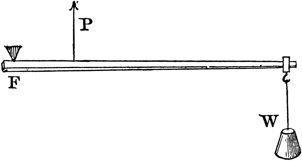
    A leg vise is a third class lever. Imagine this picture turned 90º so that the weight is at the top, and you'll have a leg vise. The parallel guide and pin serve as the fulcrum (F), the screw is the power (P), and the resulting force is applied to the board (W). In this picture the board looks like a weight, but the application of the resulting force is the same. Lifting the weight is like squeezing a board between the chop and the face of the leg.


Posting Permissions

  • You may not post new threads
  • You may not post replies
  • You may not post attachments
  • You may not edit your posts
  •