Page 1 of 2 12 LastLast
Results 1 to 15 of 18

Thread: Need rewiring help for Delta Invicta RS-15 Shaper

  1. #1
    Join Date
    Mar 2004
    Location
    Midwest
    Posts
    638

    Need rewiring help for Delta Invicta RS-15 Shaper

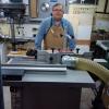
    I bought a couple of CGG Schmidt corrugated heads for my RS-15 based on recommendations from many of the good folks here. But before I can use them, I need to get the machine running. It came in working order from a shop using 460V, 3-ph. I need to run it on 230V, 3-ph. I'm good with general electrics, having completely wired 3 shops, 1 garage, and an apartment, but I'm a little out of my league when it comes to transformers. Here's what I've got...

    The first pic shows the overall wiring in the cabinet. Power (from the plug) enters from the little black terminal on the lower left. The little red terminal goes to the power switch and kill switch. The upper right unit is a GE CR353XAAA Contactor. The lower right is an Impervitran B040-0026-5 Transformer. The heavier red/brown/black wires on the upper left of the photo go to the motor.

    The second pic shows the right side of the transformer. The black wire with the red terminal connector is connected to H2, labeled 460V. H4 is labeled 230V. Part of me is hoping that rewiring this thing to run on 230V, 3-ph. is just as simple as moving that wire from H2 to H4. But my track history in the luck department says that there's more to it than that, and some other wires have to be moved around.

    I just don't want to fry anything, so I thought I'd seek the advice of the knowledgeable motor gurus here. I should emphasize knowledgeable -- while I appreciate people just trying to help, if your electrical experience stops at changing a few outlets and lamp cords, then I'd rather you pass on this one.

    Thanks!

    Keith
    Attached Images Attached Images

  2. #2
    Join Date
    Jan 2004
    Location
    Lewiston, Idaho
    Posts
    28,554
    Keith,

    Hopefully some expert will chime in. I have installed and maintained everything from radar used in air traffic control, to MR and CT scanners so I have a little knowledge BUT...I am not an electrician.

    Here's what I see.

    The transformer based on it's schematics and connections is just to step up or down one phase of the incoming AC voltage to provide a control voltage for the on/off switch. It can accept any of the labeled inputs and provide ac for control voltages for the on/off switch.

    You will notice the 3-phase AC input comes to the lower part of the contactor and the output AC comes from the contactor to the terminals at the upper left.


    First question......1) Is the motor capable of being rewired to work on 230 VAC?

    The 3-phase ac that supplies power to the motor won't be effected by the transformer so the motor needs to be capable of functioning on 3 phase 230 vac.
    Ken

    So much to learn, so little time.....

  3. #3
    Join Date
    Dec 2006
    Location
    Toronto Ontario
    Posts
    11,280
    Hi, ken is correct, in addition, the motor will have to be reconnected for 230 volts, assuming it's a dual voltage motor. The motor nameplate will indicate this information, as well as how to convert the motor to 230 volts.

    The heater elements for the starter (overload elements) will also need changing as the motor current will be twice as high on 230 volts as it is on 460 volts.

    Regards, Rod.

  4. #4
    That looks like switch wiring. It is plausible moving the one wire to the 230v contact will set up the switch for you.

    Now to the motor: it needs to be setup for the voltage you have and you do that by opening the box on the side of the motor. If you are lucky, there will be a schematic in there to change the voltage.

    Are you using phase conversion and if so, what type?
    Last edited by Loren Woirhaye; 10-23-2013 at 2:04 PM.

  5. #5
    Join Date
    Jan 2004
    Location
    Lewiston, Idaho
    Posts
    28,554
    To expand on Loren's question.

    Do you have 3 phase 220-240 VAC available? Are you working in an industrial area as most home owners don't have access to 3-phase power from the utility companies but some industrial areas do.

    Or.....do you have some type of phase conversion?
    Last edited by Ken Fitzgerald; 10-23-2013 at 5:06 PM.
    Ken

    So much to learn, so little time.....

  6. #6
    Join Date
    Feb 2003
    Location
    Bellingham, WA
    Posts
    1,933
    Open up the connection box on the motor and write down how the motor leads are connected. They should be labeled. From that, you can sometimes determine exactly how the motor is wound and how to reconfigure for lower voltage. But usually there will be a pair of diagrams showing which leads to connect for high (460) or low (230) voltage. Sometimes this is on the name plate, sometimes inside the J-box on the motor.
    JR

  7. #7
    Join Date
    Mar 2004
    Location
    Midwest
    Posts
    638
    Thanks for the reply, guys! Sorry for the slow reply. My new shop is about 35 miles from my house and it doesn't have an Internet connection yet.

    I'm running an American Rotary 20hp Rotary Phase Converter off my 230V, 1-ph mains to get 230V, 3-ph power.

    I looked for a motor plate, but I couldn't see one. There could be one on the back side. I'll have to get out a mirror and flashlight to take a look next time I'm in the shop. I'm pretty sure that it's a 230V/460V motor. It'll say on the machine plate, but I'm away from the shop and I don't have a picture of it. BTW (if it matters), it's a 7.5 hp motor.

    I do have a picture from inside the motor box. I was hoping to see a nice diagram showing how to wire for the different voltages, but instead there was no diagram and a mess of black wires. I'll have to take another look when I get back to the shop to see if I can work out what's going on with those wires.

    There's also a little fuse on the left side of that transformer. I'm not sure if that'll have to be doubled if I switch to 230V.

    Keith
    Attached Images Attached Images

  8. #8
    Join Date
    Feb 2005
    Location
    Easthampton, MA
    Posts
    986
    It all starts with the motor. The plate should state the voltages it can run at. If it gives dual voltages it will give you two options of wire connections in the the motor box. I have had three phase motors that were only 460 volts and then you have only two options. A buck and boost transformer or a good motor shop that can go into the windings and split the connections to convert it to 230 volts. On the switch you will need to change the coil on the contractor. You give so little info it's really hard to do much.

  9. #9
    Join Date
    Feb 2011
    Location
    Central WI
    Posts
    5,666
    Looks to be a nine lead motor which means dual voltage. I don't have a wiring schematic with me but you should be able to download on as all motors are generally wired the same way. The numbers on the wires look printed on rather than brass rings that can be removed so you will know which three to wire toether. Two each get attached to L1.2.3. Swap the coil and heaters and you should be able to go at 240. I have seen nine lead motors that don't run right at 240 but that is a motor problem and not normal. Dave

  10. #10
    Join Date
    Feb 2003
    Location
    Bellingham, WA
    Posts
    1,933
    Does the coil need to change if it is energized via the transformer?
    JR

  11. #11
    Join Date
    Feb 2011
    Location
    Central WI
    Posts
    5,666
    Quote Originally Posted by J.R. Rutter View Post
    Does the coil need to change if it is energized via the transformer?
    Maybe not. Depends on if the transformer feeds the coil. On my old US machines the transformer sometimes just feeds the start stop buttons. On my Euro machines it feeds both so that the machine can be sold in many different markets with the same starter. Usually 120 or 24v. The Invicta might be that way. Dave

    Edit. I thought the OP was looking to run a 240-460 transformer to the machine and the pics were of that. My bad.
    Last edited by David Kumm; 10-24-2013 at 10:06 AM.

  12. #12
    Join Date
    Mar 2004
    Location
    Midwest
    Posts
    638
    Hi guys,

    Thanks for all the info. Everything said is helping. I'm heading out to my shop in a couple of hours, so I'll try to get into the guts of it a little deeper and look a little harder for a motor plate with a wiring diagram. Hopefully, I'll have some better info by tonight.

    Keith

  13. #13
    Join Date
    Feb 2011
    Location
    Central WI
    Posts
    5,666
    Google dual voltage motor wiring and look at the pictures. You will find diagrams for WYE and Delta configurations. 440 is the same but at low voltage you will be running a delta configuration off a RPC. If the motor wants to be wired WYE it will sound horrible on delta and you will know it immediately. That has only happened to me once so it is pretty rare. WYE is used for utility 208 three phase. Dave

  14. #14
    Join Date
    Mar 2004
    Location
    Midwest
    Posts
    638
    Well, I got back to my shop today and did a little more digging. The motor did have a plate on it, but it was on the back side of the motor inside the cabinet, so you couldn't read it directly. I had to play around with my mirror, a flashlight and crappy autofocus point'n'shoot camera, but eventually after about 20 photos, I managed to get a decent shot. From there, I was able to flip it and view it on the computer. It is a 230V/460V motor, as I suspected. It was wired for 460V as per the diagram on the motor plate. I've since re-wired it to match the 230V diagram.

    IMG_1098 copy.jpgIMG_1110 copy.jpg

    I've attached another shot of the power board pulled out of it's mount. I've gone through the wiring the best that I could. Supply power enters from the lower left, through the little black plastic terminal and to the contacter on the top right. From there, the two thinner black wires rob high voltage from two of the three supply lines to supply the transformer. The transformer produces 24V at the two thinner red wires on the bottom left of the transformer. All the thinner red wires on the board are 24V and connect the switching to the relays, etc. on the contacters.

    As far as I can tell the 3-phase input (whether it be 230V or 460V) goes through the upper right contacter, then through the upper left contacter, and then through to the motor via a reversing tumbler switch. I've rewired the motor to 230V, and moved the little black wire with the red terminal plug to the 230V terminal from the 460V terminal. I don't see any reason why it shouldn't run the way it is now, but I wanted to give you guys a little time to stop me from blowing it up if I'm missing something.

    I'm out of my element when it comes to delta or wye types of 3-phase. I cant tell by the nameplate which type it would be when wired for 230V. There's a little triangle under L1 in the 460V diagram and two little triangles under L1 in the 230V diagram. The Greek symbol for delta is a triangle, but I'm not sure if that means anything or not.

    A pic of the machine...

    IMG_1108 copy.jpg

    Keith

  15. #15
    Join Date
    Feb 2011
    Location
    Central WI
    Posts
    5,666
    That is 230 delta. I'm not familiar with the starter but the inputs will be labeled L1,2,3 and the outputs to the motor T1,2,3. Don't be too afraid. Those machines are not too delicate and you can't really hurt anything permanently. Nice shaper. Dave

Posting Permissions

  • You may not post new threads
  • You may not post replies
  • You may not post attachments
  • You may not edit your posts
  •