Page 2 of 6 FirstFirst 123456 LastLast
Results 16 to 30 of 83

Thread: Dining room carver chairs - Take 2

  1. #16
    Join Date
    Dec 2016
    Location
    South West Ontario
    Posts
    1,504
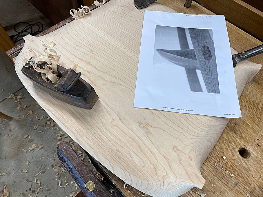
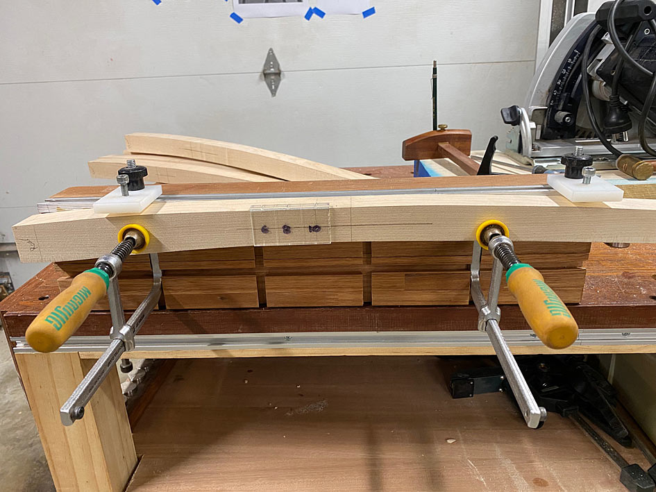
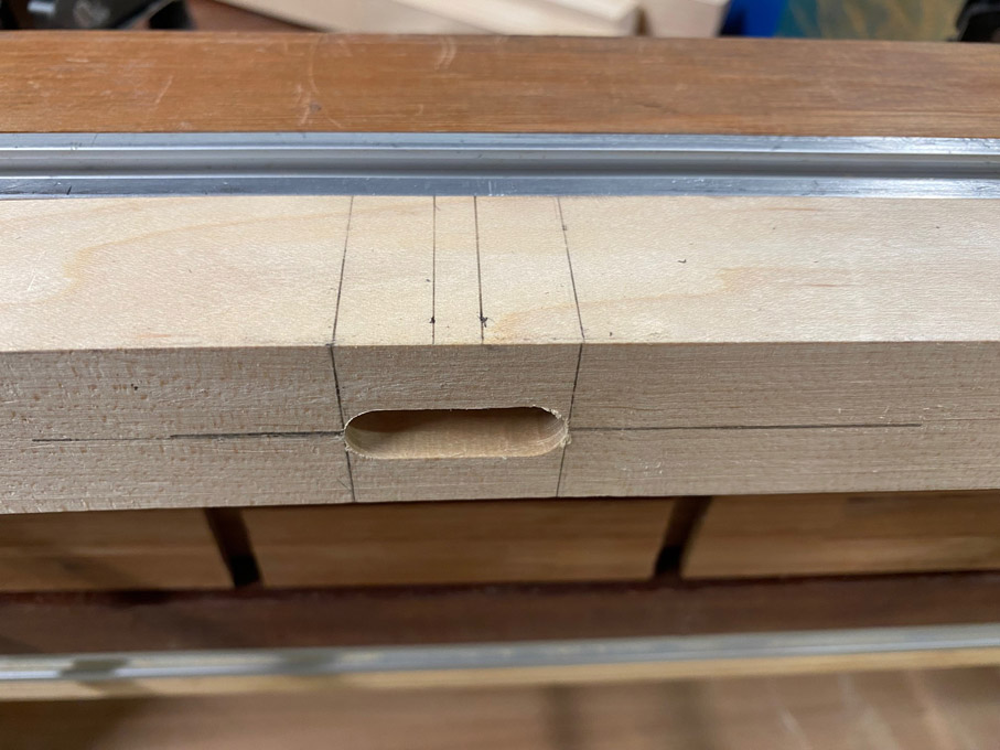
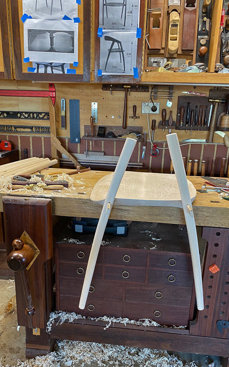
    I think the vertical tenon grain is the strongest choice. The mortice worries me however, I could not get an idea how deep the mortice is. The mortice grain is horisontal and not much of it around the tenon in the seat. It looks prone to cracking.
    While mortice depth helps the leverage is on the outer edge of the mortice.
    ​You can do a lot with very little! You can do a little more with a lot!

  2. #17
    Join Date
    Feb 2004
    Location
    Perth, Australia
    Posts
    9,497
    William, the mortice is 28mm deep.

    Regards from Perth

    Derek

  3. #18
    Join Date
    Dec 2016
    Location
    South West Ontario
    Posts
    1,504
    Such a short mortice will place most of the 50lb force on the outer top edge of the mortice. Not much wood there.
    Angling the tenon up into the mortice would put more force deeper into the seat, significantly increasing the strength.
    It would also greatly increase the supporting wood at the edge.
    You could make one of each design to test what happens.
    Your chairs will be likely little used and give them to the light people when there are!
    ​You can do a lot with very little! You can do a little more with a lot!

  4. #19
    Join Date
    Dec 2016
    Location
    South West Ontario
    Posts
    1,504
    Looking at the original chair again the supports are right across the seat bottom, carved out of the wood. The tenon is just the end of this seat support, a very strong design.
    ​You can do a lot with very little! You can do a little more with a lot!

  5. #20
    Join Date
    Feb 2004
    Location
    Perth, Australia
    Posts
    9,497
    William, I am going to disagree with you on this occasion.

    Firstly, the loose tenon lies 28mm inside the seat and 28-30mm outside (as a through tenon). This is as much depth as is used on many chairs built professionally. Plus the loose tenon is a tight fit. No play.

    Secondly, the reason for the loose tenon is that this enables the tenon grain to be orientated for maximum strength. The original chair does not.

    Regards from Perth

    Derek

  6. #21
    Join Date
    Dec 2016
    Location
    South West Ontario
    Posts
    1,504
    Derek the two designs are completely different. The weak part of your design is not the tenon but the mortice around the tenon, not much wood. Claiming the tenon depth is commonly used means nothing, you have to look at the mortice it uses. ‘Loose tenon orientates grain’ ??
    The original design is brilliant, there’s no additional mortice, the rock solid tenon goes into the rock solid mortice. PLEASE tell me you can see this!
    ​You can do a lot with very little! You can do a little more with a lot!

  7. #22
    Join Date
    Feb 2004
    Location
    Perth, Australia
    Posts
    9,497
    William, I am very aware of the issues here. In fact, I ditched the first set of seats - which had integral tenons, as per the original design - as the wood grain had run out which weakened the tenons. That was when I decided to use loose tenons, where I could control the run out. I chose straight-grained stock, and am also orientating the grain for maximum strength.

    The strength of the tenon lies with the root as well as the fit. The ideal root is integral, but this is not possible, and one must resort to a rule for sufficient strength. The rule here is 1/2 - 2/3 the thickness of the mortised piece. The seat is 40mm thick. The tenon is 30mm x 10mm (the latter is 1/3 of the 30mm leg width). Its surround is 5mm. The ideal mortice depth for the loose tenon would then be 20 - 27mm. I have made it 28mm, with 23mm buried in the seat and 5mm in the surround. The fit is tight, that is, no slop and no need for gap filling.

    It would be good to hear the opinions of others (after all, that is what these posts are all about).

    Incidentally, I had a similar discussion when I built two beds about a year ago. What I did for the rails, which also had 28mm deep mortises and loose tenons, was add a pin to each side. Is that is another option here, or just overkill?

    Regards from Perth

    Derek

  8. #23
    Join Date
    Dec 2007
    Location
    Fishers, Indiana
    Posts
    554
    Derek,

    Great to see your progress. I think the seats are beautiful.
    Can't wait to see the legs attached.

    Years ago, I made a light weight rocking chair. It was the first chair I ever attempted. I remember looking at the joinery used by Sam Maloof on his Rockers and doing a quite bad job of trying to emulate them.
    Despite that and just using screws to hold the joints together with almost no long grain to long grain, it has held together well over the years despite the abuse my son has given it.

    I have no doubt the long grain to long grain loose tenons you are using will make a solid and reliable joint.

    -Jeff

  9. #24
    Join Date
    Feb 2004
    Location
    Perth, Australia
    Posts
    9,497
    Thanks Jeff. I have almost completed the 8 legs - re-made them from scratch. More on this shortly.

    Regards from Perth

    Derek

  10. #25
    Join Date
    Feb 2004
    Location
    Perth, Australia
    Posts
    9,497
    New Legs

    Every time I sit down to write up the progress made I feel like apologising for how little there is to show for the efforts made. I have made this observation before - it is tough to copy from photos when there are no measurements to follow, but it is especially so when the piece is curved and changes shape from different angles. I keep finding new detail to add in, and it seems like a never ending carousel.


    One example, the front underside of the seat is concave and not convex. I added this, but need to do more ...


    The seats need quite a bit more work, mainly refining details. For example, the sides need to be tapered more. For later.


    For now I return to the legs.


    I did make 8 legs when building Mark 1 of the chairs, but now I am about to re-make them completely. Why? Because the first set of legs were designed for a chair which was inspired by the DC 09 Chair, but now that I am attempting to get close to this design, the legs also need to be in keeping.


    Step one was to create a template, and then mark out 8 legs. These were bandsawed close to the lines, and then cleaned up with spokeshaves ...


    The second time around is always easier, and marking out the mortises was much more efficient by measuring the front of the legs ...


    ... and then dropping the verticals ...


    This is made possible by ensuring all sides were kept square when the leg blanks were made.


    As before, the Domino was used to mortice the through tenons. The legs are clamped to a mortising fixture.


    The mortises are 30mm long and 10mm wide, and through the 30mm thick legs. Since the Domino 500 can only rout to a depth of 28mm, it was done by working half way from each side.


    The mortise needed to be marked very accurately, and to do this I used a marking jig I developed and wrote about recently ...


    The article is here: https://www.inthewoodshop.com/Powere...AMortiser.html


    It was possible to be as accurate as this for both sides and all the legs ...


    This ended with a pile of legs blanks plus mortises ..


    Early on in the build of Mark 1, I attempted to use a half-round bit on a router table to round the legs. This was a disaster as the Rock Maple blew up, leaving me with wet trousers. Looking back on this sad experience, I realised that I had literally bitten off more than I should have chewed. So I was determined to try again, but this time rout in stages, little-by-little ...


    The leg at the rear is one I attempted purely with spokeshaves. It was a miserable experience - Rock Maple is well named.


    Here are 8 semi-finished legs. The corners have been rounded, but much of the leg is still square-ish owing to the tapered profile - the legs start at 35mm at the top, are 30mm by the mortise, and end at 22mm at the feet. Consequently, there is still a whole lot of shaping still to do.


    Look closely and you can see the flats on the sides.


    There followed a lot of spokeshaving.


    A progress shot of 4 completed legs and 4 incompleted legs ...


    "Completed" really means "done for now". There is constant refining. Slowly the square becomes less so, and then round, but with imperfections, and then eventually there are just fine tracks ...


    I must admit that it is so tempting to leave it like this, where fingers can caress the tool marks ...


    This would look better on a different style of chair, and the DC 09 is better suited to a sanded finish.


    Here are two of the legs to gauge progress. Note the photo on the wall in the background for comparison (also recognise that the arm section of the legs has been left long at this stage)...


    Until next time.


    Regards from Perth


    Derek

  11. #26
    Join Date
    Feb 2020
    Location
    Camarillo, CA
    Posts
    423
    Thanks for posting. I’m enjoying following along with the design iterations and problem-solving.

    I’ve had pretty good success making octagonal hard maple legs using a jack plane for the majority of the bulk removal. That’s another option that could reduce the amount of time with a spokeshave. I agree it makes you understand the name rock maple! I find myself stopping to sharpen much more often; as soon as the blade gets a little dull the effort goes way up.

    In any case - the chairs are looking good.

  12. #27
    Join Date
    Sep 2007
    Location
    Longview WA
    Posts
    27,469
    Blog Entries
    1
    Looks great, I have forgotten to keep track of this thread. (a lot of work around the house, shop and greenhouse to keep up)

    In one of your updates you asked for any ideas:

    ... until I was loaned the largest rasp I have ever seen. Large enough to cause most here rasp-envy. It says Nicholson on it, but it appeared larger than a Nicholson #50, and far, far coarser than the 11-grain it is advertised as having. Any ideas?
    To me that looks similar to a farriers rasp, for fitting shoes on horses.

    Farriers Rasp.jpg

    jtk
    "A pessimist sees the difficulty in every opportunity; an optimist sees the opportunity in every difficulty."
    - Sir Winston Churchill (1874-1965)

  13. #28
    Join Date
    Feb 2004
    Location
    Perth, Australia
    Posts
    9,497
    Quote Originally Posted by Ben Ellenberger View Post
    Thanks for posting. I’m enjoying following along with the design iterations and problem-solving.

    I’ve had pretty good success making octagonal hard maple legs using a jack plane for the majority of the bulk removal. That’s another option that could reduce the amount of time with a spokeshave. I agree it makes you understand the name rock maple! I find myself stopping to sharpen much more often; as soon as the blade gets a little dull the effort goes way up.

    In any case - the chairs are looking good.
    Thanks for the comments, Ben.

    In this case, using a jack plane for the legs is out of the question since the legs are curved (as well as tapered).

    The reason for the router was to remove as much waste as possible, and also to create some lines to follow. Rounding the corners and creating fair curves is best for a hollow spokeshave, and I have used two, a LN and a Stanley, depending on the width of the section.

    Regards from Perth

    Derek

  14. #29
    Join Date
    Feb 2004
    Location
    Perth, Australia
    Posts
    9,497
    When I began this build, I looked at the legs of this chair and recognised that they were curved, tapered and oval. Well, oval at the top and round at the bottom ...


    I wasn't sure how to do this - the tapered oval shape. I just accepted that I would discover this as we went along.


    I began by shaping the legs in profile and cut the mortises ...


    Then knocked off the corners with a round over bit. The leg at the rear was an attempt to do all with just spokeshaves - not great. The round over provides a helpful guide ...


    This left them rectangular with rounded corners. This weekend the rectangles became tapered ovals.


    Working at the bench, holding the legs in a clamp ...


    The first step was to cover the legs in pencil scribble. The purpose here is to make it easier to see where I am working. This Rock Maple is so light in colour and difficult to pick up details.


    Some of the waste had already been removed by spokeshaves, but now the final shaping needed to take place. The tools used were a convex spokeshave and a set of convex scrapers - different sizes.


    Once sharpened, the scraper make nice shavings ...


    The scrapers also provided a template for the curves to be retained on the legs. The taper on the sides of the legs goes from 40mm at the top to 30mm at the mortice to 25mm at the feet. The edges (facing forward and rearward) is a uniform 30mm. So this meant that there was a single convex scraper for the edges and two scrapers for the sides.


    This is the difference between a scraper and the leg ...


    Running it along the leg reveals the low section through the centre ...


    As you work down, so the curve increases, and the high spot gets smaller ...


    The convex spokeshave helps out ...


    Also, angling the scraper allows a wider cutter to follow the outline of a narrower section ...


    Eventually, the scraper and the leg share the same profile ..


    Lots of work on a very humid weekend. All legs completed now ...


    Regards from Perth


    Derek

  15. #30
    Join Date
    Feb 2004
    Location
    Perth, Australia
    Posts
    9,497
    I must admit that this is an unusual build for me. I literally do not know what I am doing ... insofar as I have to keep returning to parts to refine and refine them. That is what is so time consuming. I don't always score high on being sensible, but I do on perseverance and being bloody minded!


    Today was not a work day, and I ear-marked completing the seats. The upper side was 99% done, but the underside needed fine-tuning. I have two photos to guide the shaping ...


    That one (above) is from the factory building the prototype. They screwed the legs to the seat, rather than use integrated tenons. This proved to be a great model in my case.


    The second photo is a production chair seat taken from the underside. In particular, this shows the treatment of the smoothing of the tenons and their integration with the back ...


    Lastly, I keep returning to this photo of the chair, which shows how thin the seat looks from the side. Keeping in mind that the seats started out at 50mm, and were 40mm after the plan was cut out, a great deal of tapering was necessary to achieve this look ...


    Here are the two completed seats. The seat on the left is face up, and the seat on the right is bottom up ...


    Regards from Perth


    Derek

Posting Permissions

  • You may not post new threads
  • You may not post replies
  • You may not post attachments
  • You may not edit your posts
  •