Page 5 of 6 FirstFirst 123456 LastLast
Results 61 to 75 of 83

Thread: Dining room carver chairs - Take 2

  1. #61
    Join Date
    Dec 2007
    Location
    Fishers, Indiana
    Posts
    554
    Derek,

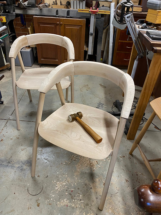
    It's a real joy to see the progress on your chairs.

    Quote Originally Posted by Derek Cohen View Post
    A question for all is how you might connect/join the arms with the legs? Note that the back will be joined angled to the sides, as per the photo.
    Derek
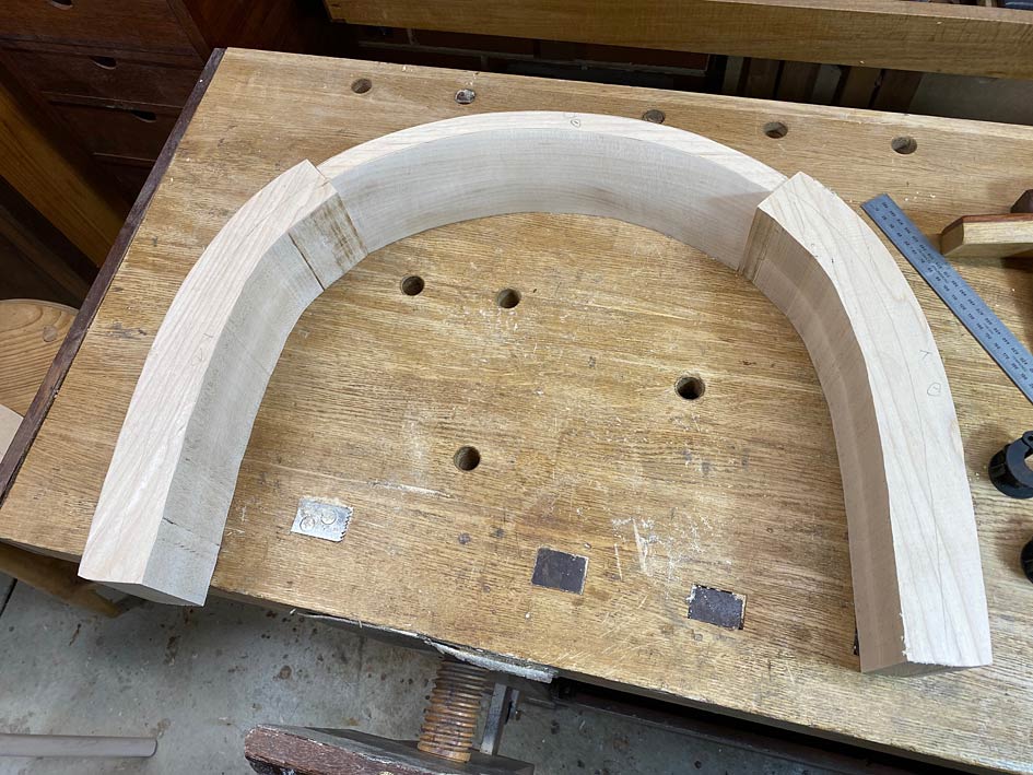
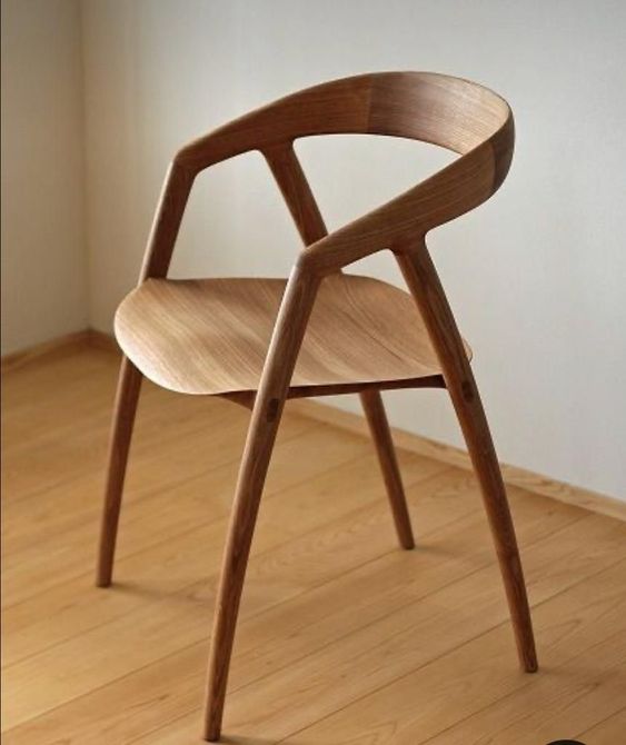
    When I had to make a similar angled back to arm joint, I ended up using several 1/8" x 2" splines. I was afraid to even attempt the tapered finger joints as you did on your Wegner chair reproduction.
    I wonder if splines between the arm to leg joint with similar wood as you used for the tenon wedges would work well.

    Look forward to seeing more.

    Regards,
    Jeff

  2. #62
    Join Date
    Mar 2014
    Location
    Los Angeles
    Posts
    1,380
    Derek, you wrapped blue tape around the tops of the legs to guide the cut - how did you know the line to mark?
    Seems like this would be very difficult to get right. The template use used helped but there was still a lot to get on the money.

  3. #63
    Join Date
    Feb 2004
    Location
    Perth, Australia
    Posts
    9,497
    Mark, first I ran lines on each side of the seat support (legs) using a template - which was placed on both sides of the seat supports ...


    I did have to estimate the ends where it was not possible to mark.

    Sawing was fine for about 6/8 of the seat supports. On two I went a little off course, but then used a rasp to level it - again using the template to determine where to do this ...


    Does that answer your question?

    Regards from Perth

    Derek

  4. #64
    Join Date
    Mar 2014
    Location
    Los Angeles
    Posts
    1,380
    Yes, though I'm glad I'm not doing it.

  5. #65
    Join Date
    Feb 2004
    Location
    Perth, Australia
    Posts
    9,497
    Arms - part 1


    The key piece is the top rail, and the key element here is the rear curve. Here it is smoothed on the belt sander. It will be a reference side for marking curves ...


    The angles I have had to guestimate have been the tilt, front and rear, of the top rail. This is what I came up with ...


    The plan is to join the arms using dowels. The Rule of Thirds applies. 3 x 3/8" dowels (3/8" = 9.5mm, which is close to the 10mm tenons used previously). Why dowels? Because they are easier to position accurately without a reference edge.


    Since a large amount of waste will be removed from the top rail and arms, through shaping, the dowels need to be positioned where they will not be cut into. The three marks on the ends of the top rail are the position for the dowels. The wooden block was a quick guide to drill vertical as it needed to be done freehand ..


    The only complication was that I had 6mm dowel centre points. It would have been easier if they were 3/8". Nevertheless ...


    Drilled for 3/8" dowels in Jarrah (I have a bucket of them), each close to 50mm (2") in length.


    Everything is still a rectangle at this stage ...


    The inside face of the top rail is shaped ...


    It is at this point that I have a re-think about the curve of the rear - it is not a fair curve and enough curve when compared with the photos of the DC 09 chair. The re-drawn curve on the left looks correct to me now, and this is what we will go with ...


    The parts are joined up as a loose fit (using undersized dowels)...


    The arm/rail combination is now placed on the arm supports and adjusted to the front and rear to determine the rear overhang and position for the front joint ..


  6. #66
    Join Date
    Feb 2004
    Location
    Perth, Australia
    Posts
    9,497
    The template I made up earlier is used to trace out the side elevations. The shaping here is approximate. The main goal is to establish the length of the arms and from arm support joint ...


    A little detail of interest: the height cut is slightly more than the front joint triangle would suggest as the final shaping requires a little extra meat to end in a curve ...


    This is now sawn to shape, except for the underside of the arm, as the mortise/tenon area needs to be determined separately for each arm ...


    Tomorrow will begin the final shaping and, hopefully, glue up of the arms.


    Regards from Perth


    Derek

  7. #67
    Join Date
    Nov 2009
    Location
    Ellsworth, Maine
    Posts
    1,809
    Holy sh** Derek! This is looking so good! What a complicated yet interesting build. You're getting so close to finish line yet still so much to work on and think about. Great build thread and look forward to seeing it through.

  8. #68
    Join Date
    Sep 2007
    Location
    Longview WA
    Posts
    27,468
    Blog Entries
    1
    Amazing

    jtk
    "A pessimist sees the difficulty in every opportunity; an optimist sees the opportunity in every difficulty."
    - Sir Winston Churchill (1874-1965)

  9. #69
    Join Date
    Feb 2004
    Location
    Perth, Australia
    Posts
    9,497
    A little more as it is getting closer.


    The first step is to align all the arms and mortices ...


    There was a lot of scribing, fitting, scribing and more fitting.


    Finally the shaping of the underside of the arms was possible as it was now possible to determine the general position of the mortises.


    The waste was removed with a bandsaw and coping saw ..


    Now the specific position for the mortices was fixed with dowel pointers ...


    Drilled and dowelled ..


    And the arms fitted to check that all will fit at the end ...


    Shaping to come.


    Regards from Perth


    Derek

  10. #70
    Join Date
    Mar 2012
    Location
    Mid coast Maine
    Posts
    479
    What an amazing project Derek. How wonderful you are sharing all that goes into it, the good the bad and the restarts. My hat is off to you.
    Jim
    Ancora Yacht Service

  11. #71
    Join Date
    Feb 2004
    Location
    Perth, Australia
    Posts
    9,497
    Many thanks Jim. It has certainly been a voyage of discovery.

    And thanks for coming along with me.

    Regards from Perth

    Derek

  12. #72
    Join Date
    Mar 2012
    Location
    Mid coast Maine
    Posts
    479
    Always a pleasure Derek, I’ve never been disappointed.
    Jim
    Ancora Yacht Service

  13. #73
    Join Date
    Feb 2004
    Location
    Perth, Australia
    Posts
    9,497
    The Arms (part 2)


    This is a last post before I return from three weeks being dragged over New Zealand mountains by my wife and her family. I used the Easter Weekend to get as much done as possible, but I needed a few more days. So there is more to come, later.


    It is helpful to remember what the aim is - as close a copy of the DC 09 chair as possible. All guidance from photos ...


    We left off here ...


    The three parts that make up the arms and top rail ..


    The top rails were shaped ...


    And shaping started on the arms ...


    Today the arms were begun.


    I find it easier to do one part as far as I can take it, then stop and repeat this with another part. When all four arms have progressed the same distance, I start with the first arm again and take it to the next stage. Then the other three to match. And so on.


    Each stage completed must be checked, and this is done by putting the parts together, to check that they balance. The two sides must remain a mirror image, and the two chairs must be identical. There are no templates to mark the lines to work towards, only the rough layout lines that appear fair to the eye.


    The arms are shaped with rasps and spokeshaves ... mainly coarse rasps - the Shinto and a 10 grain Auriou - followed with round- and flat bottom spokeshaves. Starting with the inside faces ...


    Inside faces mostly done ...


    Inside faces almost done, except for the undersides ...


    Further along - top inside and outside faces mostly done ...


    And that's it for now. More later. Thanks for keeping me company through this build.


    Regards from Perth


    Derek

  14. #74
    Join Date
    Feb 2020
    Location
    Camarillo, CA
    Posts
    423
    Looking good! Also, I got a good laugh about the “do not saw” note on the parts. I imagine fitting a complicated build like this around life and professional work requires having a good system in place to keep track of order of operations and where you are in the process.

  15. #75
    Join Date
    Mar 2014
    Location
    Los Angeles
    Posts
    1,380
    I came across these chairs online, which look to me like they might be the starting point for the people who make the chair you are making a copy off.
    Posting here to add to this great thread.

    Screenshot 2024-04-06 at 7.25.16 AM.jpg Screenshot 2024-04-06 at 7.25.43 AM.jpg Screenshot 2024-04-06 at 7.25.59 AM.jpg

Posting Permissions

  • You may not post new threads
  • You may not post replies
  • You may not post attachments
  • You may not edit your posts
  •