


Hobby woodworking has been in short supply of late. Most of it is confined to reading and thinking about projects I hope to one day begin. On the reading side of things, I've given some attention to Roubo's workbench options. I've never worked with a tail/wagon vice, however I can see some merit in them. I am considering, at some point, making a bench with one fitted.
Clearly, a tail/end vice in not required for excellent woodworking. There are plenty of other options. A bench knife, bar clamp in a face vice, holdfasts, battens etc. However, clearly highly skilled woodworkers of the 18th century took the time to make and end vice for highly detailed work such as veneer or inlay. The extent of the work of the Menuisier-Ebeniste can be seen by the link. The "classic" Roubo set up and work made using the bench can be found here
Warren was good enough to translate a section that I could not get to grips with, that section is shown in italics.
For those that work with a tails vice, do you find them useful? Are they simply of no use? Hope you enjoy the read, all comments welcome!
The tools and equipment of the cabinet-makers do the same as those of joiners for producing work, as, for example, the workbenches and the sharpening tools. But they have others which differ greatly from those of the ordinary joiners, and which consequently require a particular description. I will give a brief description of the tools which are necessary for a cabinetmaker, as well as other tools & instruments whose use is necessary in this part of woodworking.
Description of Cabinetmakers/Veneer Workers Tools
As the cabinet-makers do smaller work, they have more care to take in construction than would be normally used in other kinds of joinery. This is why there is a specific trade aside from work more commonly done, such as carpentry or joinery.
The workbench, represented in fig. 1, is a German workbench. It is not certain that it was invented in Germany, or, what is more probable, created by German cabinet-makers, who are in great number in Paris. This bench, like all the others, is composed of four legs, a bottom and a top. At the extremity of which is placed a tail vice, used to retain the wood in place on the benchtop. This is done by means of two hooks or chins of iron. One of which is placed in the benchtop, and the other in the tail vice, and which is changed according to the position of the work at hand.
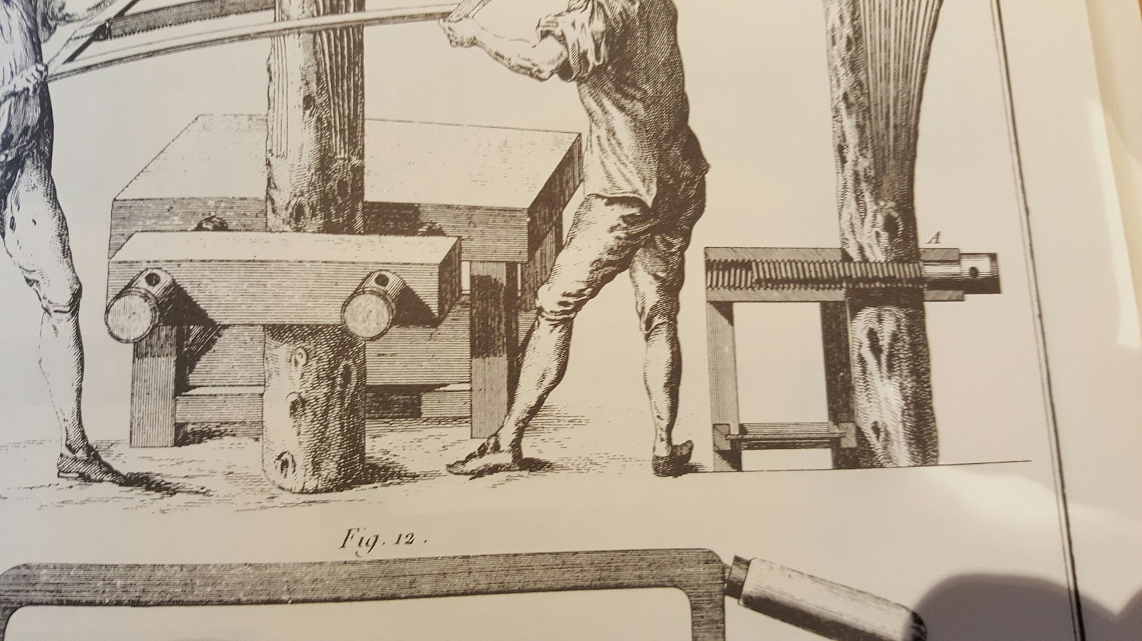
The tail vice, which forms the most essential part of the workbench, is 14 or 15 inches in length, about 3 ½ inches wide and a thickness equal to that of the benchtop, which is usually 4 inches. This vice, shown in fig 5, 6, 7, 8, 10 & 12. The diagrams show an inside view of the moving screw, its nut, and is composed of four sections A, B, C, D fig 7. Also an end section E, fig 5, and fore section, F, fig 6 and 8. The iron hook passes through the fore section which may be seen in fig. 6 which is an open view of the vice, with section B removed, with the place of the hook, indicated by dotted lines. Fig 8, which represents the longitudinal screw and the mortise proper to place the hook.
The piece F is presented to the end of the screw, located within the tail vice and has 8 to 10 inches of travel. It is retained in place by a rod G, fig.6 and 7, into which it enters into a notch. This rod G is used to fasten the underside of the vice at the place of the hook, and to compress the tongues of the rear piece, which, without the tail of the piece, would bear alone the whole weight of the vice
The tongues of the rear part B, fig 7. must have little height, in order to manage the force of the cheek which holds them, the solidity of which is increased by screws with a countersunk head. Place it at a distance, as can be seen in this figure, which represents the transverse section of the box, and of a section of the box. See also Figure 10, which represents the side of the construction To see the box, with the bar GG, which supports it.
The head E of the box, FIG. 5, 6 & 8, is assembled in the upper part and in the lower one with a groove and tongue, and is arrested with screws, or at least glue-dowels. The top piece A, passes into notch over the main part F, and is similarly secured, and that from below is assembled to the tongue and mortise.
Piece B of the rear, fig. 7, is fastened with screws on the head of the box and on the main part, as can be seen in FIG. 12, which represents the box seen from behind. The front piece, which serves as a door, attaches similarly with screws, which are stopped only with the nut.
The screw which serves to move this box, is made of iron, as well as its nut, which is the strongest; However, when we want to save cost, we know the wooden screw and the nut in iron, furnished with lead can be used as I can explain below.
Whether the screw is made of wood or iron, it is necessary that it be of the whole length of the box, so that it also carries the end of the collar, there is then less fatigue when it presses against the box and consequently block F against the benchtop. See Fig. 8. The collar of the screw must be stuck in the head of the box, to open and close it. Which is done by observing a groove of about ¼ inch deep in the collar, into which two keys of iron or copper, or even of very hard wood, can be entered, which stop the screw and the box of a fixed manner. See Figs. 6 & 8, which represent the section of the screw and keys which stop its collar
When an iron screw is used, ¾ of an inch diameter is sufficient for it. When it is made of wood, it is necessary, in order that it be solid, that it should have be at least 1 ⅜ inches.
The nut for the wooden screw is formed like a babbitt bearing. The hole in the iron nut is made way oversized and molten lead alloy is poured in with a piece of threaded wood in place in order to form the threads of the nut. There are 4 holes made from the outside edges of the nut so that the lead alloy has keys to keep it from turning inside the iron part when in use. The pattern screw is covered with a thin coating of clay and glue mixture both to keep the screw from burning and to provide clearance when the vise is in use. Before pouring, the clay mixture is also applied around the outside of the nut in a ring around the wooden screw to form a dam so the alloy does not flow out at the openings of the nut.
The iron hooks or chins used in the tail vice, are about ⅞ ths of an inch square, a length equal to the thickness of the workbench, plus ⅞ ths of an inch. They also have one or two springs to the sides so that they can hold up to such a height that it is judged to be appropriate. See Figs. 2 & 3.
The hook which is located in the benchtop, changes, as is required in holes that are 4 inches of distances from each other, and 1 ¾ inches from the edge of the workbench, so that the middle of their width is just at the midpoint of the screw. Refer to fig.5.
The holes for the hooks, are arranged in a sloping manner, counter to that of the tail vice, as can be seen in Fig. 6, so that when the wood is pressed between the hooks, the force of the pressure does not force them out of place, and that the piece e, fig. I, which is taken in-between, does not escape
A leg vice is fitted to the leg of the bench. Also, for the sake of convenience, a second, moving vice is fitted. This moves on a tongue fixed to the lower rail and groove in the underside of the benchtop. This second vice moves from one end of the workbench to the other, as it is deemed appropriate, and is removed by sliding it towards the fixed vice where the tongue is cut short.
These vices open to any position required. To keep them open both from the bottom and from the top, a runner is fixed into the bottom of the vice, fig. 4. It is pierced by several holes, in which is placed an iron pin to stop them at the required distance.
In addition to the vices described a smaller vice is mounted with iron screws, the face of the vice is equal to the thickness of the benchtop. See Fig. 11, where I have represented a section of this vice, with its screw and its nut. I have also indicated, by punctuated lines, the place of the hooks or chins, the groove of the moving vice. The joints of the legs are also shown, and are only three quarters of the thickness of the table, which is cleaner, and is much better than to make them pass through, as is the custom on a joiners bench.
Instead of using iron screws on these face vices, we can use wood. The side of the workbench can be tapped. At the end of the vice screw there is normally a head for passing a lever to the operate the screw. Sometimes the screws have no head, and are tapped in all their length.
Only included to show a bench edge tapped for a twin screw vice
When not in use, parts of this vice are sometimes placed in drawers under the lower shelf of the workbench, like those H, I, L, fig. 1, which is very convenient to store an infinite number of things. Moreover, these drawers are less hinderance than those which are placed immediately below the workbench, as is the custom.


 Reply With Quote